February 24, 2022  Expand to read article below Expand to read article belowThe generation of Enhanced Mid-Range Family of PIC16 devices include mTouch™ Sensing technology. CCS demonstrates our uses for Capacitive Touch Development Board and compiler libraries in a fun hands-on application.
The CCS Capacitive Touch board uses the PIC16LF727 device for creating human touch applications and utilizing contact sensitive hardware. Instead of using mechanical switches or buttons that can break, the Capacitive Touch pads are activated by placing a human finger over the pad and the user's natural electrical properties generate the needed response or change.
Cut development time by utilizing specific Capacitive Touch functions built into the CCS C Compiler. The #USE TOUCH_PAD library reduces roughly 500 lines of assembly to 1 line of C code! A full version of the CCS C Compiler is available with the development kit.
The CCS Exercise tutorial contains 14 example programs that step the user through Capacitive Touch applications. Use the 16 on-board programmable capacitive pads and LCD to quickly develop "touch" applications. In addition, the board is equipped with *Tag Connect footprint for ICSP™ programming and a ICD-U64 that can be used with all Flash-supported PIC® MCU devices.
For additional information or to order today, go to: www.ccsinfo.com/Touch
Like us on Facebook. Follow us on Twitter.
About CCS:
CCS is a leading worldwide supplier of embedded software development tools that enable companies to develop premium products based on Microchip PIC® MCU and dsPIC® DSC devices. Complete proven tool chains from CCS include a code optimizing C compiler, application specific hardware platforms and software development kits. CCS' products accelerate development of energy saving industrial automation, wireless and wired communication, automotive, medical device and consumer product applications. Established in 1992, CCS is a Microchip Premier 3rd Party Partner. For more information, please visit https://www.ccsinfo.com.
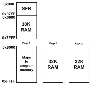
PIC® MCU, MPLAB® IDE, MPLAB® ICD2, MPLAB® ICD3 and dsPIC® are registered trademarks of Microchip Technology Inc. in the U.S. and other countries. | February 24, 2022 Expand to read article below The 24 bit PIC® architecture allows for very easy access from most instructions to locations 0x0000 to 0x1FFF. There are some additional instructions to move data from a working register to a location in the 0x2000 to 0x7FFF range. Note that 0x0000 to 0x07FF (or 0x0FFF on some parts) are special function registers, not general RAM.
Some devices have more than 30K of RAM. For these devices a special method is required to access the RAM above 30K. This extended RAM is organized into pages of 32K bytes each. The only way to access that RAM from assembly is to set a page register to identify the RAM page and then use indirect addresses from 0x8000 to 0xFFFF. Note that the first page is used to map program memory into the RAM address space. The other pages are the extended RAM.
From C, the compiler will allocate variables into the first page of extended RAM only. To access additional memory special functions must be used.
The basic functions to access that RAM are:
write_extended_ram(p, addr, ptr, n); Writes n bytes from ptr to extended RAM page p starting at address addr.
read_extended_ram(p,addr,ptr,n); Reads n bytes from extended RAM page p starting at address addr to ptr.
The first page is 1.
Example Code:
write_extended_ram(1,0x100,WriteData,8); //Writes 8 bytes from WriteData to //addresses 0x100 to 0x107 of
//extended RAM page 1.
read_extended_ram(1,0x100,ReadData,8); //Reads 8 bytes from addresses 0x100 //to 0x107 of extended RAM page 1
//to ReadData.
Like us on Facebook. Follow us on Twitter.
About CCS:
CCS is a leading worldwide supplier of embedded software development tools that enable companies to develop premium products based on Microchip PIC ® MCU and dsPIC ® DSC devices. Complete proven tool chains from CCS include a code optimizing C compiler, application specific hardware platforms and software development kits. CCS' products accelerate development of energy saving industrial automation, wireless and wired communication, automotive, medical device and consumer product applications. Established in 1992, CCS is a Microchip Premier 3rd Party Partner. For more information, please visit https://www.ccsinfo.com.
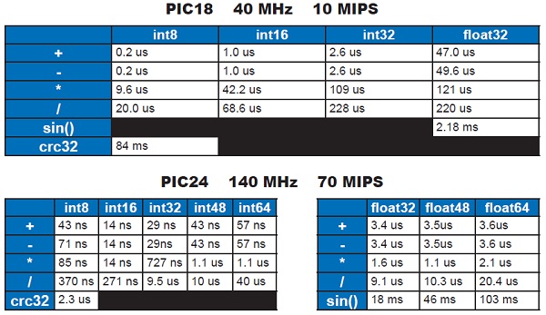
PIC ® MCU, MPLAB ® IDE, MPLAB ® ICD2, MPLAB ® ICD3 and dsPIC ® are registered trademarks of Microchip Technology Inc. in the U.S. and other countries. | February 24, 2022 Expand to read article below The PIC® instructions are very deterministic in the time they take. There are exceptions, but in general a instruction takes 4 clocks (or 2 on some 24 bit chips) and if there is a change in the program counter it take s twice as long. Counting instructions in the LST file is one way to figure out the time code takes. Consider this example from the LST file:

The IF statement takes instruction times if a==b or 4 otherwise. On a PIC18 this is 16 clocks. So if the chip oscillator (fosc) is 40mhz. Then the instruction time is 4/40000000 or 100ns. This IF statement takes 300ns or 400ns to execute. The two assignments take 400ns so in total if a==b then it takes 700ns or 400ns otherwise.
IDE users can use the code profiling tool to find out how long functions take to execute or to time how long it takes to get from one point in code to another.
Use code like the following To do timing manually:
setup_timer_1(t1_internal|t1_div_by_4); // 1us tick
set_timer1(0);
for(i=1;i<=100;i++) { a=b; }
overhead=get_timer1();
set_timer1(0);
clear_interrupt(int_timer1);
for(i=1;i<=100;i++) { a=b+c; }
time=get_timer1();
time=time-overhead;
if(interrupt_active(int_timer1))
printf("\r\nOVERFLOW");
printf("\r\nus=%6.2lw\r\n",time);
Unsigned 8 bit operations for math operations are quite fast and floating point is very slow. If possible consider fixed point instead of floating point.
For example, instead of "float cost_in_dollars;" do "long cost_in_cents;". You can also get the compiler to do the math for you by using a declaration like "long fixed(2) cost_in_dollars;"
Consider a lookup table for trig formulas instead of real time calculations (see EX_SINE.C for an example).
Note all times will vary depending on memory banks used and sometimes for multiply, divide and float operations the actual numbers will affect the time.
Like us on Facebook. Follow us on Twitter.
About CCS:
CCS is a leading worldwide supplier of embedded software development tools that enable companies to develop premium products based on Microchip PIC ® MCU and dsPIC ® DSC devices. Complete proven tool chains from CCS include a code optimizing C compiler, application specific hardware platforms and software development kits. CCS' products accelerate development of energy saving industrial automation, wireless and wired communication, automotive, medical device and consumer product applications. Established in 1992, CCS is a Microchip Premier 3rd Party Partner. For more information, please visit https://www.ccsinfo.com.
PIC ® MCU, MPLAB ® IDE, MPLAB ® ICD2, MPLAB ® ICD3 and dsPIC ® are registered trademarks of Microchip Technology Inc. in the U.S. and other countries. | April 29, 2022 Expand to read article below Sometimes there is a need to debug multiple processors in the same system. It is possible if you use the CCS ICD units to use multiple ICD units on the same PC. This allows you program or debug different target devices in separate processors concurrently.
By default the PCW IDE will only open one instance and additional files you attempt to edit appear as separate tabs. Although the IDE can only manage one project at a time it is possible to have multiple instances of the IDE open at the same time.
Procedure:
* Connect two ICD units and target devices.
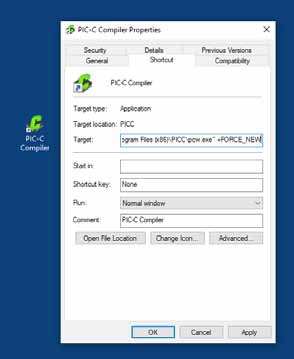
* Right click on the desktop icon for the IDE and select PROPERTIES.
* At the end of the target line, after the " if there is one, add a space followed by: +FORCE_NEW
* Start up the IDE by double clicking on the icon and load the first project and start debugging. With both ICD units connected you will be prompted (by serial number) for the ICD unit to use. You can use the CCSLOAD utility to give each unit a friendly name. You can also go the "Configure Port" button the control panel to switch ICD units.
* Double click again on the IDE icon and this time select the second project. You can start that debugger as well.
Like us on Facebook. Follow us on Twitter.
About CCS:
CCS is a leading worldwide supplier of embedded software development tools that enable companies to develop premium products based on Microchip PIC ® MCU and dsPIC ® DSC devices. Complete proven tool chains from CCS include a code optimizing C compiler, application specific hardware platforms and software development kits. CCS' products accelerate development of energy saving industrial automation, wireless and wired communication, automotive, medical device and consumer product applications. Established in 1992, CCS is a Microchip Premier 3rd Party Partner. For more information, please visit https://www.ccsinfo.com.
PIC ® MCU, MPLAB ® IDE, MPLAB ® ICD2, MPLAB ® ICD3 and dsPIC ® are registered trademarks of Microchip Technology Inc. in the U.S. and other countries. | April 29, 2022 Expand to read article below Introducing support added for debugging dsPIC33CH devices for both the master and slave cores to the CCS C Compiler and IDE using the CCS ICD-U80 or ICD-U64 device programmers. This support will be available starting with Compiler version 5.094 and ICD firmware version 3.42 and newer. In addition to debugging the slave core with the CCS tools the slave core can also be programmed starting with the previously mentioned version. Both of these features will aid in developing code for the dsPIC33CH dual core devices.
When debugging there are three setups that can be done. First debug only the master core, second debug only the slave core, or third debug both the master and slave core at the same time. When debugging the slave core the master core's configuration bit need to be set so that the slave core can be debugged. At minimum the S1_ISOLAT, S1_DEBUG and S1_ICSPx, x being the debug pin to use for the slave core, should be set. The S1_ISOLAT configuration fuse allows the slave core to operate even if the master core hasn't set the SLVEN bit in the MSI1CON register, enabling the slave core to run, the S1_DEBUG configuration fuse enables the slave core debugger and the S1_ICSPx configuration fuses sets which S1MCLRx, S1PGCx and S1PGDx pins are being used to debug the slave core.
When debugging both the master core and slave core at the same time it requires that two instances of the CCS C Compiler and IDE be running, two device programmers, and the development board will have to have two ICD connectors on it connected to different MCLR, PGC and PGD pins, one for the master core and one for the slave core. To run two instances of the CCS C Compiler and IDE +FORCE_NEW needs added to the target line of the icon used to launch the IDE, for example:
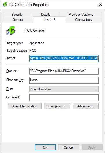
With the above change when using that icon to start the IDE will cause a new instance of the IDE to start allowing for more the one instance to be running. Once there are two instances of the IDE running the master core project should being opened in one and the salve core project should be opened in the other. Next starting with the master core project, build it with the appropriate slave core configuration fuses set and start the debugger. Assuming both ICDs are connected to the PC a selection box similar to the following should pop up:
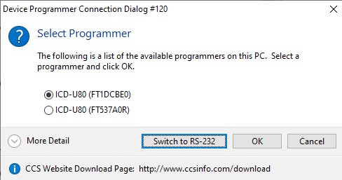
Select the ICD that is connected to the master core's programming/debugging pins and select 'OK'. If you're not sure which ICD is connected to the master core you may want to disconnect the ICD connect to the slave core debugging pins from the PC and then start the master core's debugger, then when the master core's debugger is loaded the slave core ICD can be reconnected to the PC. Once the master code program debugger is loaded, switch to the CCS IDE instance with the slave core project, build it and start its debugger. Once it's done loading both the master and slave core can be debugged at the same time.
One thing to be aware of the master code debugger using the MCLR pin of the PIC. If the master core's debugger pulls that pin low to reset the master core it will also reset the slave core. So if the master core debugger is reset or the program if reloaded when the slave core is also being debugged, the slave core's debugger needs to be reset to synchronize it with the slave core.
Like us on Facebook. Follow us on Twitter.
About CCS:
CCS is a leading worldwide supplier of embedded software development tools that enable companies to develop premium products based on Microchip PIC ® MCU and dsPIC ® DSC devices. Complete proven tool chains from CCS include a code optimizing C compiler, application specific hardware platforms and software development kits. CCS' products accelerate development of energy saving industrial automation, wireless and wired communication, automotive, medical device and consumer product applications. Established in 1992, CCS is a Microchip Premier 3rd Party Partner. For more information, please visit https://www.ccsinfo.com.
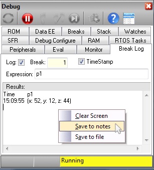
PIC ® MCU, MPLAB ® IDE, MPLAB ® ICD2, MPLAB ® ICD3 and dsPIC ® are registered trademarks of Microchip Technology Inc. in the U.S. and other countries. | April 29, 2022 Expand to read article below Save to notes
The option to "Save to notes" is in the right-click menu of multiple debug windows which will append the selected data (such as break log or RAM data) to the end of the notes file associated to the project.
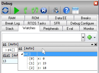
 Drag and drop "watch items"
Have an important watch variable that is in the middle or at the bottom of your watch list? You can now drag and drop watch items within the watch window to reorder them by your preference.
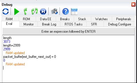
 Change RAM
If during debugging you want to change the value of a variable or just see the result of a complex expression use the EVAL tab in the debugger. If you use the = operator then RAM is actually changed.
 Viewing RAM
Looking directly at the RAM data is easy with the RAM tab in the debugger. You might not know if you highlight some data you can use right click to interpret that data in various formats or just copy the data to your notes file.
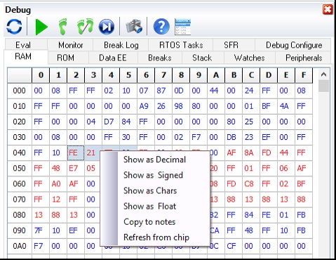
There are a lot of helpful features in the debugger, many can be explored be reviewing the various tabs and doing some right clicking. If you have suggestions for more features please let us know.
Like us on Facebook. Follow us on Twitter.
About CCS:
CCS is a leading worldwide supplier of embedded software development tools that enable companies to develop premium products based on Microchip PIC ® MCU and dsPIC ® DSC devices. Complete proven tool chains from CCS include a code optimizing C compiler, application specific hardware platforms and software development kits. CCS' products accelerate development of energy saving industrial automation, wireless and wired communication, automotive, medical device and consumer product applications. Established in 1992, CCS is a Microchip Premier 3rd Party Partner. For more information, please visit https://www.ccsinfo.com.
PIC ® MCU, MPLAB ® IDE, MPLAB ® ICD2, MPLAB ® ICD3 and dsPIC ® are registered trademarks of Microchip Technology Inc. in the U.S. and other countries. | July 13, 2022 Expand to read article below The CCS tool suite has a number of features to help adding serial numbers to product firmware. In your source code the primary method uses the pre-procssor directive #serialize. The CCS device Adding Serial Numbers to Production Images. The CCS tool suite has a number of features to help adding serial numbers to product firmware. In your source code the primary method uses the pre-processor directive #serialize. The CCS device programmers must be used to take advantage of this feature. It works by adding a special comment line to the hex file.
Location of the serial number
The usual way to handle the location is to use a const declaration like one of the following:
const int32 serial_number;
const char sn[7];
Then in #serialize add something like id=serial_number.
You can also place the serial number in EEPROM by specifying an address like:
dataee=0x10
Format
Usually the format can be figured out from the const however you can specify it using one of:
binary=x - x is the number of bytes.
string=x - x is the number of characters.
unicode=n - If n is a 0, the string format is normal unicode.
For n>0 n indicates the string number in a USB descriptor.
Serial number source
There are four ways to specify where the serial number comes from:
file="filename.txt" - The file x is used to read the initial serial number from, and this file is updated by the ICD programmer. It is assumed this is a one line file with the serial number. The programmer will increment the serial number.
listfile="filename.txt" - The file x is used to read the initial serial number from, and this file is updated by the ICD programmer. It is assumed this is a file one serial number per line. The programmer will read the first line then delete that line from the file.
next="x" - The serial number X is used for the first load, then the hex file is updated to increment x by one.
prompt="text" - If specified the user will be prompted for a serial number on each load. If used with one of the above three options then the default value the user may use is picked according to the above rules.
Logging
log=xxx - A file may optionally be specified to keep a log of the date, time, hex file name and serial number each time the part is programmed. If no id=xxx is specified then this may be used as a simple log of all loads of the hex file.
Examples:
//Prompt user for serial number to be placed at address of serialNumA
//Default serial number = 200
int8 const serialNumA=100;
#serialize(id=serialNumA,next="200",prompt="Enter S/N")
//Adds serial number log in seriallog.txt
#serialize(id=serialNumA,next="200",prompt="Enter S/N",
log="seriallog.txt")
//Retrieves serial number from serials.txt
#serialize(id=serialNumA,listfile="serials.txt")
//Place serial number at EEPROM address 0, reserving 1 byte
#serialize(dataee=0,binary=1,next="45",prompt="Put in S/N")
//Place string serial number at EEPROM address 0, reserving 2 bytes
#serialize(dataee=0, string=2,next="AB",
prompt="Put in S/N")
USB_STRING_DESC is a table of USB strings and is read by the CCS C Compiler's USB stack when the host PC reads a string from the PIC ®. A value of 3 is passed to the Unicode parameter, to tell the #serialize that the serial number should be encoded as a Unicode string and that it should overwrite the 4th string in USB_STRING_DESC (the first string in USB_STRING_DESC is 0). In the device descriptor for your USB device, the field identifying which string to use for the serial number should also have been set to 3.
#serialize(id=USB_STRING_DESC, unicode=3, prompt="SN#")
Using a CCS device programmer but not the compiler?
The same features can be used by editing the hex file using the CCSload utility. Select the FILE page and then SERIAL NUMBERS and you can fill in manually the parameters:
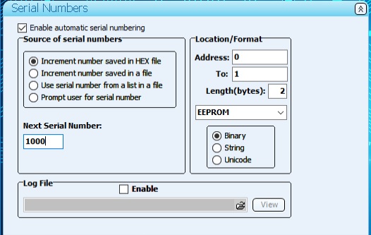
Save or Save-As the hex file and the serial number works as it did with the compiler directives.
Like us on Facebook. Follow us on Twitter.
About CCS:
CCS is a leading worldwide supplier of embedded software development tools that enable companies to develop premium products based on Microchip PIC ® MCU and dsPIC ® DSC devices. Complete proven tool chains from CCS include a code optimizing C compiler, application specific hardware platforms and software development kits. CCS' products accelerate development of energy saving industrial automation, wireless and wired communication, automotive, medical device and consumer product applications. Established in 1992, CCS is a Microchip Premier 3rd Party Partner. For more information, please visit https://www.ccsinfo.com.
PIC ® MCU, MPLAB ® IDE, MPLAB ® ICD2, MPLAB ® ICD3 and dsPIC ® are registered trademarks of Microchip Technology Inc. in the U.S. and other countries. | July 13, 2022 Expand to read article below The CCS IDE has an easy way to make a copy of a project. The feature is accessed by using FILE > COPY PROJECT. The dialog box looks like this:
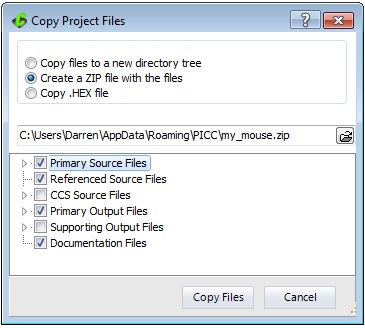
The lower selection allows you to select an entire group of files or expand the group and select specific files. The references source files include files supplied with the compiler like stdlib.h. The supporting output files are files used by the IDE and not usually opened outside the IDE. Documentation files are any files attached to the project using the navigation bar.
The location entry in the center allows you to specify the destination. Use the folder icon on the right to browse and/or create a new location.
The functions are as follows:
Copy files to a new directory tree
This simply makes a copy of the designated files to a new directory location. The .ccspjt file usually references the project files using a relative path so the project should compile right in the new location.
Create a ZIP file with the files
This makes a zip file with the designated files. This is ideal for a archive or if you need to send a project to CCS for analysis.
Copy .HEX file
Despite the name this function can quickly make a copy of any combination of files to another location. For example you may need to make a copy of the project hex file to a public location where others can use it for testing or production. By default just the project hex file is selected however if you select some other files that now becomes the default so you can quickly use this function to make the same copy when needed.
Like us on Facebook. Follow us on Twitter.
About CCS:
CCS is a leading worldwide supplier of embedded software development tools that enable companies to develop premium products based on Microchip PIC ® MCU and dsPIC ® DSC devices. Complete proven tool chains from CCS include a code optimizing C compiler, application specific hardware platforms and software development kits. CCS' products accelerate development of energy saving industrial automation, wireless and wired communication, automotive, medical device and consumer product applications. Established in 1992, CCS is a Microchip Premier 3rd Party Partner. For more information, please visit https://www.ccsinfo.com.
PIC ® MCU, MPLAB ® IDE, MPLAB ® ICD2, MPLAB ® ICD3 and dsPIC ® are registered trademarks of Microchip Technology Inc. in the U.S. and other countries. | July 13, 2022 Expand to read article below Many newer Microchip PIC® microcontrollers have re-programmable peripheral pins (RP). These pins allow the user to dynamically allocate peripherals to these pins, such as external interrupts, input capture, PWM, serial, timers and more. This offers the designer great flexibility when designing a product since the functionality of these pins can be changed at run-time. The data sheet for a device will list he pin assignments and these pins are denoted as either RPxx or RPIxx, where xx is the RP pin number. Pins that are RPIxx can only be programmed as an input (timer input, serial input, interrupt input, etc), whereas RPxx pins can be programmed either as an input or output (PWM output, serial output, etc).
Static Assignments in C
The static method for assigning I/O pins to a peripheral is the #pin_select directive. The #pin_select directive is a preprocessor directive for assigning I/O pins to peripherals and is executed before main() starts. The syntax for this command is as follows:
#pin_select function=pin
A list of functions and pins that can be used with the #pin_select directive is located in the device's header file near the top of the file, opening the device's header file (like 18F25K42.h) and searching for #pin_select is the quickest way to find them. The following is an example of how to assign pins to the UART1 RX and TX pins:
#pin_select U1TX=PIN_C6
#pin_select U1RX=PIN_C7
When using RP pins with a peripheral library, such as #use rs232(), the #pin_select must come before the #use directive, for example:
#pin_select U1TX=PIN_C6
#pin_select U1RX=PIN_C7
#use rs232(UART1, baud=9600, stream=U1)
There is a special method for assigning the peripheral pins is inside the #use pwm and #use capture directives. Future compiler release may allow this in other #use directives as well. Here is an example:
#use pwm(CCP1, output=PIN_B0)
The above will make the assignment of PIN_B0 as the CCP1 output pin.
Dynamic Pin assignments
In addition to #pin_select the CCS C Compiler also provides the pin_select() function for assigning pins to a peripheral. The pin_select() function can be used to assign, reassign and unassign pins to/from a peripheral at run-time. This allows the flexibility of using the same pin for multiple peripherals or using pins as both peripheral pins and I/O pins. The basic pin_select() function uses the following syntax: pin_select("function", pin);. The functions and pins are the same as what is used with the #pin_select directive, the only difference being that the function is passed as a constant string. The following is an example of how to assign pins to the UART1 peripheral:
pin_select("U1TX", PIN_C6);
pin_select("U1RX", PIN_C7);
To unassign a pin from a peripheral depends on whether it an input peripheral or an output peripheral.
To unassign a pin from an output peripheral is done as follows:
pin_select("NULL", PIN_C6); //unassign PIN_C6 from output peripheral.
To unassign a pin from an input peripheral is done as follows:
pin_select("U1RX", FALSE); //unassign pin from U1RX input peripheral.
Because of how output peripherals are assigned to RP pins it is possible to assign multiple pins to the same output peripheral when using the pin_select() directive. For example the following will assign multiple pins to the CCP1 peripheral:
pin_select("CCP1OUT", PIN_B0);
pin_select("CCP1OUT", PIN_B1);
This method of tying several pins to the same output can only be performed with the pin_select() function, #pin_select cannot be used to do this.
A more advanced form of the pin_select() directive is as follows:
pin_select("function", pin, unlock, lock);
In order to change the pin assignments at run time the pins must be first specifically unlocked to prevent run away code from changing a pin assignment. The optional unlock and lock are used to specify whether to do or not to do the unlock and lock procedures, TRUE does the procedure and FALSE doesn't to the procedure. When the lock/unlock parameters are not specified in the function both are performed by default. These optional parameters are most useful when using the pin_select() function to assign multiple peripheral pins sequentially. For example the following is an example of how to assign the UART1 TX and RX pins at run time:
pin_select("U1TX", PIN_C6, TRUE, FALSE);
pin_select("U1RX", PIN_C7, FALSE, TRUE);
Alternate pin assignments
Before the RP pins came out some chips allowed select peripherals to have multiple (usually just two) pins that can be assigned. This is done either by a fuse (like CCP2B3 and CCP2C1) or using an internal register.
In the case the selection is by fuse the #fuse directive must be inserted in the code and then the compiler will treat that pin as a peripheral. For example:
#fuses CCP2C1
In the case that the register assignments are made by register the built in functions will have an option for the assignment. See the header file for the device. The UART assignments are made with the #use rs232 by specifying one of the alternate pins.
Like us on Facebook. Follow us on Twitter.
About CCS:
CCS is a leading worldwide supplier of embedded software development tools that enable companies to develop premium products based on Microchip PIC ® MCU and dsPIC ® DSC devices. Complete proven tool chains from CCS include a code optimizing C compiler, application specific hardware platforms and software development kits. CCS' products accelerate development of energy saving industrial automation, wireless and wired communication, automotive, medical device and consumer product applications. Established in 1992, CCS is a Microchip Premier 3rd Party Partner. For more information, please visit https://www.ccsinfo.com.
PIC ® MCU, MPLAB ® IDE, MPLAB ® ICD2, MPLAB ® ICD3 and dsPIC ® are registered trademarks of Microchip Technology Inc. in the U.S. and other countries. | October 4, 2022 Expand to read article below The PIC16F1614 family of devices is currently the only PIC® MCU family that has a built in Math Accelerator with Proportional-Integral-Derivative (PID) Module. This module is a mathematics module that can perform a variety of operations, most prominently acting as a PID controller.
The module accomplishes the task of calculating the PID algorithm by utilizing user-provided coefficients along with a multiplier and accumulator. The main benefit of using the hardware module is for doing the PID calculation much faster than it can be done in software. For example when running the PIC® from the 32 MHz internal oscillator the built-in HW PID function was measured to take 12.8 us, compared to a software PID function which was measure to take 216 us. This is approximately 1/16 of the time.
The following are the built-in functions that have been added for the Math Accelerator with PID module:
* setup_pid() - used to setup the PID module and set the user-input coefficients.
* pid_get_result() - used to input the set point and feedback from the external system to the PID module, start the calculation, and to retrieve the result to input in the external system.
* pid_read() - used to read various PID module registers.
* pid_write() - used to write various PID module registers.
* pid_busy() - used to check if PID module is busy or not-busy, finished, with calculation.
The Math Accelerator with PID module can be setup for three basic functions PID calculation, 16-bit unsigned add and multiple and 16-bit signed add and multiple. Both of the add and multiple modes can also be setup to accumulate the output.
When setup for PID mode the user-input coefficients, K1, K2 and K3, are calculated from the three classic PID coefficients Kp, Ki and Kd with the following equations:
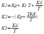
T is the sampling period.
The following is an example of how to setup and use the Math Accelerator with PID module in PID mode:
void main(void) {
pid_struct_t PIDOutput;
unsigned int16 ADCReading;
signed int16 K1 = 7, K2 = -6, K3 = 0;
unsigned int16 SetPoint = 500;
unsigned int16 PWMDuty;
setup_pid(PID_MODE_PID, K1, K2, K3);
//Setup ADC
setup_adc_ports(sAN3, VSS_VDD);
setup_adc(ADC_CLOCK_INTERNAL);
set_adc_channel(3);
//Setup PWM 3
setup_timer_4(T4_CLK_INTERNAL | T4_DIV_BY_32, 249, 1); //1ms period, from 32 MHz
set_pwm3_duty(0); //0% duty
setup_pwm3(PWM_ENABLED | PWM_OUTPUT | PWM_TIMER4);
while(TRUE) {
delay_ms(50);
ADCReading = read_adc();
pid_get_result(SetPoint, ADCReading, &PIDOutput);
PIDOutput.u &= 0x07;
if(PIDOutput.u >= 4) //PIDOutput is negative, set PWMDuty to Minimum
PWMDuty = 0; else if(PIDOutput.u != 0) //PIDOutput > Maximum, set PWMDuty to Maximum
PWMDuty = 1000; else if(PIDOutput.l > 1000) //PIDOutput > Maximum, set PWMDuty to Maximum
PWMDuty = 1000; else
PWMDuty = PIDOutput.l;
set_pwm3_duty(PWMDuty); } }
When the Math Accelerator with PID module is setup for one of the add and multiple mode the operation is preformed as follows:
OUTPUT = (A + B) * C
The multiple value, C, is set with the K1 option that is passed setup_pid() function, and the two add values, A and B, are passed as the set_point and input parameters to the pid_get_result() function. For example the following is how to setup the Math Accelerator with PID module in add and multiply mode:
int16 C = 100;
int16 A, B;
pid_struct_t Result;
//setup for add and multiple mode and set multipler
setup_pid(PID_MODE_UNSIGNED_ADD_MULTIPLY, C);
//get add and multiple result
pid_get_result(A, B, &Result);
The PIC16F1614 family of devices is available in the IDE compilers and the PCM command-line compilers starting with version 5.045. They come in 14 and 20 pin packages with flash memory of 4048 or 8192 instructions. Additionally they have four 8-bit timers, three 16-bit timers, 8 or 12 analog inputs, two CCP modules, two 10-bit PWM modules and 1 CWG module, which can be used in conjunction with other modules, CCP or PWM for example, to generate a Half-Bridge or Full-Bridge PWM. |
|


