Frequently Asked Questions
Creating a Project with the PIC Project Wizard
- Select User Toolbar -> Project Wizard from the ribbon along the top of the main window or select File -> New -> Project Wizard / Project 24 Bit Wizard from the menu bar. In the prompt that appears, choose the directory and file name in which to save the project.

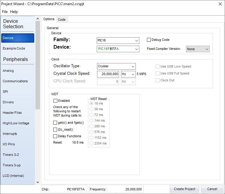
- When the Project Wizard window appears, the list on the left-side will display all of the modules and other features that can be modified for the current project and selected PIC® MCU or PIC® DSC. The Options tab on the right-side of the window displays the settings that can be modified for the selected module. The Code tab will display the code generated from the current module settings.

| Project Wizard Modules and Features | |
|---|---|
| Module | Purpose |
| Device | Select PIC® MCU or PIC® DSC and oscillator frequency. Enable Watch Dog Timer and selection of the time-out period. |
| Example Code | Check any function on this page such as Blink LED to generate a fully functional sample program. |
| Analog | Select analog pins and settings for voltage range, resolution, and clock speed. |
| Communications | Enable RS-232 and I2C subsystems, along with selecting pins, speeds, and other transmission options. |
| SPI | Enable SPI modules along with Master/Slave, mode, and clock settings. |
| Drivers | Select additional IC chip devices connected and include driver files. |
| Header Files | Select header files to include in a project. |
| High/Low Voltage | Enable Voltage Detection along with setting the voltage levels required to trip the system. |
| Interrupts | Select events that cause interrupts. |
| I/O Pins | Select I/O pins' purpose and enable pull-up resistors. |
| Timers 0-2 | Enable Timers 0, 1, and 2, along with selecting a clock and timer resolution. |
| Timers 3-up | Enable Timer 3 on PCH PIC® MCUs along with selecting a clock and timer overflow resolution. |
| LCD (Internal) | If there is a Segment LCD Driver present, selection of the LCD running mode and segment pins used will be available. |
| LCD (External) | Enable Character LCD along with selecting pin connections and address locations on the LCD. |
| Capacitive Touch | Enable Capacitive Touch and select the channel. |
| RTCC | Enable Real-Time Clock/Calendar (RTCC) along with setting the time and an alarm. |
| CCP/Vref | Enable Capture, Compare, and PWM subsystems along with setting the reference voltage levels, output configuration, and shutdown options. |
| Comparator | Select any comparators to be used. |
| USB | Enable USB along with setting the transmit and receive sizes. |
| TCP/IP | Use TCP/IP along with e-mail, HTTP server, HTTP client, Telnet server, and WiFi. |
| MOD Bus | Enable MOD Bus along with setting the status, device addresses, and communication pins and speed. |
| CAN Bus | Enable CAN Bus along with setting the communication rate and devices being used. |
| Bootloader | Use a bootloader at either the start or end of program memory. |
| Advanced Options | Select where the opening brace will appear. Restart WDT during calls to delay. Select one fuse per line with comments. Add default fuses to header file. |
| Fuses | Include Fuses along with setting code protected and write protected options. |
NOTE: The 24 Bit Wizard uses the same options as above, but may be listed under different headings.
- After all the modules and features are setup, click Create Project and the wizard will generate code for the project and save it in the directory specified earlier.
For additional help using the PIC Project Wizard, contact CCS Technical Support.


