Frequently Asked Questions
How do I connect the LOAD-n-GO to my PIC® MCU hardware?
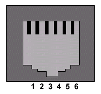
The LOAD-n-GO has a RJ-12 connector with a RJ-12 cable to connect to target devices. To add a RJ-12 connection to your hardware, use the pin-out below:

| LOAD-n-GO to Target Connections | ||
|---|---|---|
| Load- n-Go |
Target | Pin Description |
| 1 | 6 | Pin B3 on target PIC® MCU or PIC® DSC - C Aware Real-Time Debugging (Optional) |
| 2 | 5 | Pin B6 on target PIC® MCU or PIC® DSC - ICSP™ Clock |
| 3 | 4 | Pin B7 on target PIC® MCU or PIC® DSC - ICSP™ Data |
| 4 | 3 | Ground (GND) |
| 5 | 2 | Power (VDD)
|
| 6 | 1 | MCLR
|
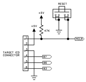
- The LOAD-n-GO draws its power directly from the USB port or from 4 AA batteries while being used for hand-held programming. However, the connection between pin 5 on the LOAD-n-GO and pin 2 on the target device should be left intact. One reason for this is because the LOAD-n-GO uses this connection to pull up voltage values. Another reason is because the LOAD-n-GO is capable of supplying +2.5V, +3.3V, or +5.0V to the target board. This can be done by opening the case of the LOAD-n-GO and placing a jumper on the correct jumper pins next to the ICD connector.

Target ICD Circuit Schematic
- In order to use in-circuit programming and debugging, the I/O pins B6 and B7 are reserved on the PIC® MCU or PIC® DSC. If debugging is not going to be used on the target device, pins B6 and B7 can be used in the target circuit. If pins B6 and B7 are used in the target circuit, ensure the circuit has high impedance during the programming process. However, some PIC® MCUs or PIC® DSCs do not use pins B6 and B7 for programming and debugging. Always check the datasheet to find the proper programming and debugging pins. The table below lists some of the PIC® MCUs that use different programming pins.
| Programming/Debugging Pins | ||
|---|---|---|
| PIC® MCU | Clock Pin | Data Pin |
| PIC12F629 | GP1 | GP0 |
| PIC12F675 | GP1 | GP0 |
| PIC12F683 | GP1 | GP0 |
| PIC16F630 | RA0 | RA1 |
| PIC16F676 | RA0 | RA1 |
| PIC16F684 | RA0 | RA1 |
| PIC16F688 | RA0 | RA1 |
- Pin B3 is an optional pin connected to the LOAD-n-GO that allows use of the monitor feature while debugging. If pin B3 is used in the target circuit or is not connected to the LOAD-n-GO, the target can still be programmed and debugged, except without use of the monitor feature. When debugging, disabling the userstream feature will ignore the connection between pin 1 on the LOAD-n-GO and pin 6 on the target device. Older versions of the debugger software require that if the monitor is not used, the pin connection on the ICD connector needs to be pulled high at all times. While pin B3 is recommended for the monitor feature, any pin on a PIC® MCU or PIC® DSC can support this feature.
- The MCLR pin is used for both programming and debugging. While programming, the MCLR pin will have +13V supplied to it, or +5.0V while programming a PIC18J® MCU, PIC24® MCU, or dsPIC® DSC. The 47K resistor to +5.0V is sufficient isolation to protect the PIC® MCU or PIC® DSC from the +13V. However, if anything else is connected to the MCLR pin, be sure the +13V will not damage or interfere with the connected device.
- The LOAD-n-GO is not capable of programming using the Low Voltage Programming mode. Programs being written to the target devices should have the NOLVP fuse set.
- If using the LOAD-n-GO to debug a target device, the target device needs to have an active oscillator running. If the LOAD-n-GO is only being used to program a target device, the LOAD-n-GO generates a clock signal that is used to program the PIC® MCU or PIC® DSC without the need of a running oscillator.
- Some PIC® MCUs are not capable of debugging with the standard version of the part. In order to debug, a specific ICD version of the chip will be needed. The table below lists some of the PIC® MCUs that require ICD Headers.
| ICD Debugging Headers | |
|---|---|
| PIC® MCU | PIC® MCU-ICD |
| PIC10F200/2/4/6 | PIC16F505-ICD |
| PIC10F220/2 | PIC16F506-ICD |
| PIC12F508/509 | PIC16F505-ICD |
| PIC12F510 | PIC16F506-ICD |
| PIC12F519 | PIC16F526-ICD |
| PIC12F609/HV609 | PIC16F616-ICD |
| PIC12F615/HV615 | PIC16F616-ICD |
| PIC12F629 | PIC12F675-ICD |
| PIC12F635 | PIC16F636-ICD |
| PIC12F675 | PIC12F675-ICD |
| PIC12F683 | PIC12F683-ICD |
| PIC16F505 | PIC16F505-ICD |
| PIC16F506 | PIC16F506-ICD |
| PIC16F526 | PIC16F526-ICD |
| PIC16F610/HV610 | PIC16F616-ICD |
| PIC16F616/HV616 | PIC16F616-ICD |
| PIC16F627A/628A | PIC16F648A-ICD |
| PIC16F630 | PIC16F676-ICD |
| PIC16F631 | PIC16F690-ICD |
| PIC16F636 | PIC16F636-ICD |
| PIC16F639 | PIC16F636-ICD |
| PIC16F648A | PIC16F648A-ICD |
| PIC16F676 | PIC16F676-ICD |
| PIC16F677 | PIC16F690-ICD |
| PIC16F684 | PIC16F684-ICD |
| PIC16F685/687 | PIC16F690-ICD |
| PIC16F688 | PIC16F688-ICD |
| PIC16F689/690 | PIC16F690-ICD |
| PIC16F716 | PIC16F716-ICD |
| PIC16F785/HV785 | PIC16F785-ICD |
| PIC18F13K50 | PIC18F14K50-ICE |
| PIC18F14K50 | PIC18F14K50-ICE |
| PIC18LF13K50 | PIC18LF14K50-ICE |
| PIC18LF14K50 | PIC18LF14K50-ICE |
For additional help connecting the LOAD-n-GO to your hardware, contact CCS Technical Support.


