

USB Interface Made Simple with Project Wizard
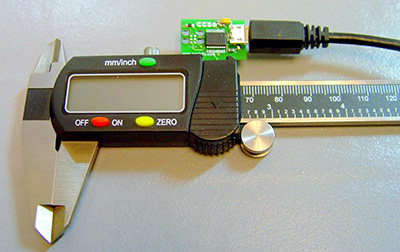
This project will make use of a diagnostic interface on a common digital caliper to display the results to the PC. The CCS C-Aware IDE Compiler will utilize the Project Wizard tool to easily generate code for a USB interface to this existing product. Follow the simple steps below to create code quickly!
Setting up
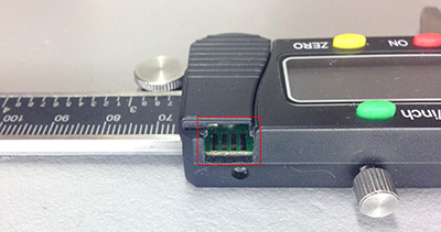
Notice that there are four pins on the interface of the digital caliper. First, a bit of effortless reverse engineering is needed to determine the data format, using a little scope probing it becomes clear that one pin is battery ground; one is the battery +3V; and the other two are used for data sending 24 bits every 110ms. The bit time is around 300us, however, every 4 bits there is an extra half millisecond gap. Here are three traces of the data at different scope zooms:


'Trace A' is clock and 'Trace C' is data. The results indicate the clock line goes low, then the data line changes, finally the clock rises and the data is assumed to be clocked in. This is known as "SPI Mode Three". A pecularity in the data is that the data line always returns high on each bit which may draw less current.
Interpreting the data when the caliper is at 0:
000000000000000000000001
When at 0.1":
000100110000000000000001
It seems the LSB (least significant bit) is sent first and the last bit is always 1. Some additional testing shows the 1 changes to 0 when the mode is switched to metric, and if distance goes negative, the last 4 bits are 1001. Flipping the bit order and showing the sign results 0.1":
+11001000 or in decimal +200
The resolution of the data is then .0005" per increment.
Hardware Design
A simple hardware design starts with selecting an inexpensive device such as the PIC16F1459 for its built-in USB. The simple schematic is as follows:
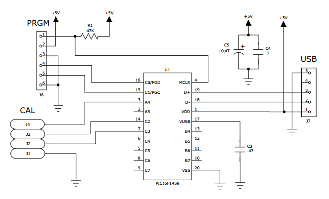
An available analog input can read a measurement of battery voltage by connecting to the +3V.
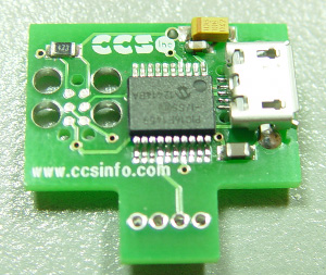
The challenge in the hardware design is connecting to the caliper pins. The opening slot is 0.31" wide x 0.4" deep x 0.12" thick. A 0.062" PCB with contacts soldered on that compress to under 0.06" will work. The Digikey part number 1003-1010-1-ND contact works well. The example design PCB looks like this:

Project Wizard setup
One of the easiest ways to begin an USB application is through the Project Wizard. Begin by opening the CCS C-Aware IDE Compiler. Close all open files by selecting 'File' then 'Close All'. Next open up a new file through the Project Wizard by selecting 'File' then 'New' and 'Wizard'. The Wizard will then require a project name and location.
On the opening screen of the Wizard, select the device "PIC16F1459" and the clock should be set to INTERNAL 48mhz with the 'Full USB' checked as indicated in Figure 1.

In the Left Margin, select 'USB' and check 'Enable the USB' as shown in Figure 2. The hardware design is powered by the USB at all times, so leave 'Connection Sense Pin' at 'None'. Also leave the VID/PID blank so it uses the CCS default VID/PID. Type in a device manufacturer and name. ("CCS" and "CALHACK" shown as example only.) This will be the name that appears in the PC Device Manager.

There are different USB protocols for 'Device Class'. Select the first option 'Communication Device Class (CDC, Virtual COM port). This protocol is easiest to use and at the PC will make the USB port look like an RS232 COM port. 'Human Interface Device Class (HID)' interface is mainly used for devices like a mouse or keypad. For HID the data transfer rate is limited to 8 bytes per packet. 'Bulk USB' mode is commonly used for high speed devices, like a video camera, and requires custom Windows drivers to use.
The USB Project Wizard is complete. Before setting up the SPI, it is necessary to manage the voltage levels from the caliper. The highest level from the clock and data is about 1.5V; therefore, run them into comparators while using the comparator outputs to drive the SPI. The comparator can use an internal reference voltage called FVR as the trip point. Comparator setup is provided in Figure 3.

To set up the voltage reference (FVR), use the CCP/Vref page as shown in Figure 4.


Now, as shown in Figure 5, select SPI to set up the SPI port. Set the port count to 1 and then set the clock 'CLK pin' to C1OUT (comparator 1 output) and 'DI pin' C2OUT. In 'Settings', select to the 'Slave' option and set the 'Mode' to 3 with the number of 'Bits' as 24 and 'First bit' to LSB as described in Figure 5.

Now to setup the analog pins. In the left margin, select 'Analog'. The three pins used in the hardware design are battery voltage, and the two comparator inputs - marked C1, C2 & C3 as shown in Figure 6.

Next, setup to use the newer stream operators for character I/O. Select 'Header Files' in the left margin of the Wizard and check to include the definitions for IOS (ios.h) as shown in Figure 7.

Generating Code
The 'Project Wizard' is ready to generate code. Ensure the 'Create Project' button is clicked at the lower right. All the tedious work is done by the Wizard, and all that is left is to fill in some logic.
Read data like this:
The following code will output a minus sign if needed and then clear that bit in the data:
Outputing the number to a half-milimeter indication is easy:
Outputing an endl adds a return/line feed to the end of line.
The caliper sends repeated data, so every data packet sent is not needed. Therefore, some code is needed to wait for the lull between packets before doing the spi_xfer(). This example waits for 8 samples 100us apart where C2OUT is idle.
Put it all together into the following main program. Note: All the setup code was inputed by 'Project Wizard'.
Programming the board
Program the board by first connecting an ICD unit (the CCS ICD-U80 is recommended) to the PC. Then connect the new PCB to the ICD. In this demonstration a 'Tag Connect' cable was used.
Using the CCS C-Aware IDE Compiler, click 'Build & Run' from the main 'Compile' ribbon to compile the program and program our PIC16F1459 chip on our board. The chip should be programmed at this point and ready for us to test!
To test, disconnect the 'Tag Connect' cable, attach a USB Cable, then plug the PCB into the caliper. Upon connecting example USB board to the PC, it will want to find drivers. The correct drivers are identified by the VID/PID. If using the CCS default values, use the CCS supplied .INF files to teach Windows how to react to this device. The .INF files are found in a directory like this (depends on your installation):
In the IDE select 'Tools', 'Serial Port Monitor', and set the COM port to the newly created caliper port (CALHACK).
The USB Wizard generated code for the hard part...now you can apply the Wizard for your own USB application.
Hardware Information and References:
| $25 |
| $15 |
| Out of Stock | $119 |
| Out of Stock | $34.95 |


