| View previous topic :: View next topic |
| Author |
Message |
bulut_01
Joined: 24 Feb 2024
Posts: 317


|
|
 Posted: Mon Feb 26, 2024 12:00 pm Posted: Mon Feb 26, 2024 12:00 pm |
 |
|
The discussion on this subject is going well. There is another issue I want to ask. I want to use 18f25k40 FVR hardware. My settings are as follows.
| Code: | setup_vref(VREF_ON | VREF_ADC_4v096);
SETUP_DAC(DAC_VSS_VDD | DAC_OUTPUT); |
Although I should see around 4 volts from the DAC output, I cannot get any output. Is there something else I missed other than these settings? |
|
 |
bulut_01
Joined: 24 Feb 2024
Posts: 317
|
|
| Posted: Mon Feb 26, 2024 11:26 pm |
|
|
| Does anyone have any ideas about FVR hardware not working? |
|
|
Ttelmah
Joined: 11 Mar 2010
Posts: 20001
|
|
| Posted: Tue Feb 27, 2024 2:35 am |
|
|
Several things.
First you don't show any line setting the output level for the DAC.
You need a DAC_write. The DAC1CON1 register (which sets the output)
defaults to 0 on boot.
Then why 4v?. You do realise you are routing the Vref to the ADC, not
the DAC?. You have the DAC operating from the supply. If your supply
is 3.3v (which your earlier posts say), you cannot select 4.096 as a
Vref output. The maximum is always just a little under the supply. So
even if you set the DAC to 31, the maximum you could see would be
3.19v.
From the data sheet:
| Quote: |
1. Fixed Voltage Reference output cannot exceed VDD.
|
|
|
|
temtronic
Joined: 01 Jul 2010
Posts: 9606
Location: Greensville,Ontario
|
|
| Posted: Tue Feb 27, 2024 5:53 am |
|
|
I wonder if Proteus will give him 4 volts...using a 3 volt supply ?.. 
Until we see the results form the OP running the I2C Scanner program, I have to assume this code is all in a Proteus simulation. |
|
|
bulut_01
Joined: 24 Feb 2024
Posts: 317
|
|
| Posted: Tue Feb 27, 2024 7:06 am |
|
|
| Ttelmah wrote: | Several things.
First you don't show any line setting the output level for the DAC.
You need a DAC_write. The DAC1CON1 register (which sets the output)
defaults to 0 on boot.
Then why 4v?. You do realise you are routing the Vref to the ADC, not
the DAC?. You have the DAC operating from the supply. If your supply
is 3.3v (which your earlier posts say), you cannot select 4.096 as a
Vref output. The maximum is always just a little under the supply. So
even if you set the DAC to 31, the maximum you could see would be
3.19v.
From the data sheet:
| Quote: |
1. Fixed Voltage Reference output cannot exceed VDD.
|
|
Can you help me with this? My goal is to get constant voltage. Is it more accurate to get it with DAC or ADC output? How exactly are the ccs configuration settings for this? |
|
|
temtronic
Joined: 01 Jul 2010
Posts: 9606
Location: Greensville,Ontario
|
|
| Posted: Tue Feb 27, 2024 7:32 am |
|
|
OK, we need to know what 'constant voltage' ??
Post with a value for the 'constant voltage' and the allowable range it can be.
IE: 5.00 volts, + 0.5, -0.2 .
So this example means constant voltage can be 4.800 to 5.500 and be withing the specifications. |
|
|
Ttelmah
Joined: 11 Mar 2010
Posts: 20001
|
|
| Posted: Tue Feb 27, 2024 8:09 am |
|
|
As Jay says, accuracy is everything on this.
ADC output????. No such thing.
The DAC is just a resistive divider. The Vref is only +/-4% accurate. The
DAC is even worse (+/-5 LSb). Neither of these is even remotely an
accurate source. Slightly better than guessing, but not by much!....
Accuracy on references costs money. You don't magically get supplied
with an accurate voltage source by a cheap PIC. A typical 0.1% Vref will
cost several times the cost of the PIC. Go more accurate, and this price
shoots up. |
|
|
bulut_01
Joined: 24 Feb 2024
Posts: 317
|
|
| Posted: Tue Feb 27, 2024 8:12 am |
|
|
| The reason I ask this question is that the circuit is powered by the battery, I need to measure the voltage of the battery, so I need to adjust gnd_fvr. These CCS configuration settings are driving me crazy. |
|
|
Ttelmah
Joined: 11 Mar 2010
Posts: 20001
|
|
| Posted: Tue Feb 27, 2024 8:33 am |
|
|
It won't give you a terribly good result. You don't adjust anything. What
you do is simply enable the FVR (this is actually 1.024v - the higher outputs
are using an op-amp multiplier). Don't feed it to the peripherals, just set the
ADC to use the supply as it's reference, then read the FVR _channel_ with
the ADC. So if you read this as (say) 328, then the supply voltage is about
(1.024/328)*1024 = 3.19v. However this is +/- 0.1276v, so between 3.05
and 3.3v. Very poor accuracy indeed.
This is the best you can do without an external Vref. This is described by
Microchip in their application note AN1072A (in this case for a chip with a
0.6v reference). The 0.6v reference here is much more accurate than the
one in your PIC. |
|
|
bulut_01
Joined: 24 Feb 2024
Posts: 317
|
|
| Posted: Tue Feb 27, 2024 9:05 am |
|
|
| Ttelmah wrote: | It won't give you a terribly good result. You don't adjust anything. What
you do is simply enable the FVR (this is actually 1.024v - the higher outputs
are using an op-amp multiplier). Don't feed it to the peripherals, just set the
ADC to use the supply as it's reference, then read the FVR _channel_ with
the ADC. So if you read this as (say) 328, then the supply voltage is about
(1.024/328)*1024 = 3.19v. However this is +/- 0.1276v, so between 3.05
and 3.3v. Very poor accuracy indeed.
This is the best you can do without an external Vref. This is described by
Microchip in their application note AN1072A (in this case for a chip with a
0.6v reference). The 0.6v reference here is much more accurate than the
one in your PIC. |
Thank you for this information. Finally, can you write the FVR CCS configuration settings here? |
|
|
Ttelmah
Joined: 11 Mar 2010
Posts: 20001
|
|
| Posted: Tue Feb 27, 2024 10:41 am |
|
|
You don't.
As I said the point is you just read it with the ADC.
| Code: |
#bit FVREN = getenv("bit:FVREN")
FVREN=TRUE; //this allows us to turn on the FVR without selecting it
setup_adc(ADC_CLOCK_DIV_128 ! ADC_LEGACY_MODE | ADC_TAD_MUL_2, VSS_VREF); //gives 4uSec acquisition at your clock rate using supply as REF
set_adc_channel(FVR_CHANNEL); //select the FVR channel to read
int16 adcval=read_adc();
int32 supplymV=1048576/adcval; //gives the supply voltage in integer mV
|
I've avoided using FP maths, by working in mV. So with my earlier example
you would get 3196. |
|
|
bulut_01
Joined: 24 Feb 2024
Posts: 317
|
|
| Posted: Tue Feb 27, 2024 11:17 am |
|
|
| Ttelmah wrote: | You don't.
As I said the point is you just read it with the ADC.
| Code: |
#bit FVREN = getenv("bit:FVREN")
FVREN=TRUE; //this allows us to turn on the FVR without selecting it
setup_adc(ADC_CLOCK_DIV_128 ! ADC_LEGACY_MODE | ADC_TAD_MUL_2, VSS_VREF); //gives 4uSec acquisition at your clock rate using supply as REF
set_adc_channel(FVR_CHANNEL); //select the FVR channel to read
int16 adcval=read_adc();
int32 supplymV=1048576/adcval; //gives the supply voltage in integer mV
|
I've avoided using FP maths, by working in mV. So with my earlier example
you would get 3196. |
thank you my friend thank you |
|
|
bulut_01
Joined: 24 Feb 2024
Posts: 317
|
|
| Posted: Mon Mar 04, 2024 4:48 pm |
|
|
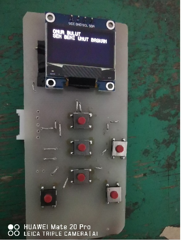
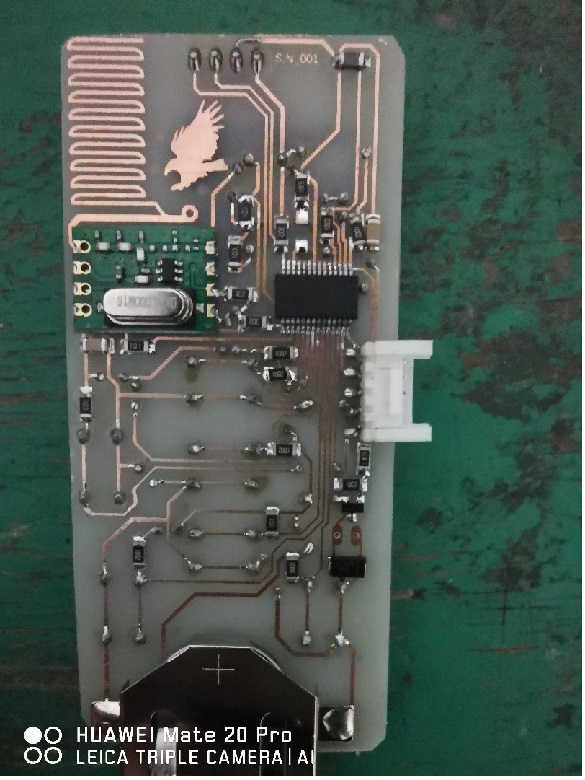
I would like to thank my friends who helped me here. OLED i2c worked in real circuit in terms of hardware.
 |
|
|
temtronic
Joined: 01 Jul 2010
Posts: 9606
Location: Greensville,Ontario
|
|
| Posted: Mon Mar 04, 2024 6:03 pm |
|
|
wow , I'm impressed ! I can't SEE SMT parts let alone SOLDER them !!
happy you got it working . |
|
|
bulut_01
Joined: 24 Feb 2024
Posts: 317
|
|
| Posted: Mon Mar 04, 2024 6:09 pm |
|
|
 |
|
|
|


