 |
 |
| View previous topic :: View next topic |
| Author |
Message |
SalihLabs
Joined: 27 May 2020
Posts: 8
Location: Ontario, Canada


|
| dsPIC33 HSPWM, phase-shift PG2 relative to PG1 not working |
 Posted: Tue May 30, 2023 11:35 pm Posted: Tue May 30, 2023 11:35 pm |
 |
|
Hi all,
I'm using the dsPIC33CH512MP508, a dsPIC with a master and slave core. Currently using PCWHD 5.093.
The HSPWM configuration settings are based on the Microchip code example on github: https://github.com/microchip-pic-avr-examples/dspic33ck-power-pwm-phase-shift
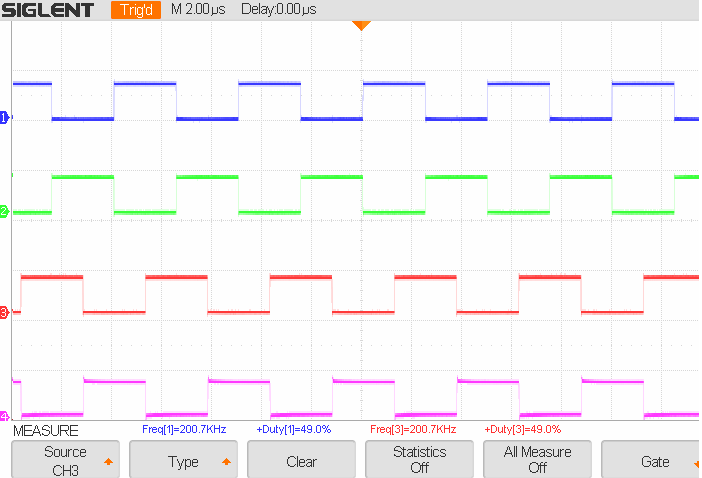
I am able to generate a complimentary signal on PG1 and PG2, but unable to phase shift PG2 relative to PG1:

The example code on github shows what the phase shifted PG2 should look like:
| Code: |
void HSPWM_init(void)
{
// setup PG1
setup_hspwm_unit(1, HSPWM_ENABLE | HSPWM_USES_MASTER_CLOCK | HSPWM_HIGH_RESOLUTION_MODE |
HSPWM_COMPLEMENTARY | HSPWM_INDEPENDENT_EDGE_MODE |
HSPWM_SINGLE_TRIGGER_MODE | HSPWM_SOC_SELF_TRIGGERED );
#byte PG1EVTL = getenv("SFR:PG1EVTL") // PG1TRGSEL[2:0]
#byte PG1IOCONH = getenv("SFR:PG1IOCONH")
#byte PG1IOCONL = getenv("SFR:PG1IOCONL")
PG1EVTL |= 0x03; // PGxTRIGC is the PWM Generator Trigger Output
// PG1IOCONH |= 0x00; // UPDMOD = 0b00, TRGMOD = 0b0, SOCS = 0b0000
// PG1IOCONL |= 0x3000; // OSYNC = 0b00, OVRDAT = 0b00, OVRENL = 1, OVRENH = 1: 0b 0011 0000 0000 0000 = 0x3000
// setup PG2
setup_hspwm_unit(2, HSPWM_ENABLE | HSPWM_USES_MASTER_CLOCK | HSPWM_HIGH_RESOLUTION_MODE |
HSPWM_COMPLEMENTARY | HSPWM_INDEPENDENT_EDGE_MODE | HSPWM_BUFFER_UPDATE_SLAVED_IMMEDIATE |
HSPWM_RETRIGGERABLE_MODE | HSPWM_SOC_PWM1_5_PG1_OR_PG5 );
#byte PG2CONH = getenv("SFR:PG2CONH")
#byte PG2IOCONH = getenv("SFR:PG2IOCONH")
#byte PG2IOCONL = getenv("SFR:PG2IOCONL")
PG2CONH |= 0x01; // SOCS[3:0] = 0b0001 Start Of Cycle: PG1 selected trigger output triggers PG2 SOC
// must force disable all other irrelevant channels, otherwise you cant use shared IO pins
setup_hspwm_unit(3, HSPWM_DISABLE);
setup_hspwm_unit(4, HSPWM_DISABLE);
setup_hspwm_unit(5, HSPWM_DISABLE);
setup_hspwm_unit(6, HSPWM_DISABLE);
setup_hspwm_unit(7, HSPWM_DISABLE);
setup_hspwm_unit(8, HSPWM_DISABLE);
// set duty cycle
set_hspwm_duty(1, duty);
set_hspwm_duty(2, duty);
// set period
set_hspwm_period(1, pwmPeriod);
set_hspwm_period(2, pwmPeriod);
hspwm_update(1);
hspwm_update(2);
// start hspwm module
delay_us(200);
setup_hspwm(HSPWM_CLOCK_AFPLLO | HSPWM_CLOCK_DIV_BY_2, pwmPeriod);
}
|
To vary the phase-shift in the main while loop, I tried both "set_hspwm_trigger_c" and modifying the PG1TRIGC SFR directly to no avail.
| Code: |
// SET Trigger limit
//set_hspwm_trigger_c(1, (unsigned int16)*(0.25*pwmPeriod));
#byte PG1TRIGC = getenv("SFR:PG1TRIGC")
PG1TRIGC = (unsigned int16)*(0.125*pwmPeriod);
//phase_adjust();
// Update
hspwm_update(1); // **
hspwm_update(2); // **
|
Any ideas? |
|
 |
temtronic
Joined: 01 Jul 2010
Posts: 9377
Location: Greensville,Ontario
|
|
| Posted: Wed May 31, 2023 5:52 am |
|
|
curious as the example code works...
I was thinking 'compiler bug' but... noticed a 0.125 floating point number....
PG1TRIGC = (unsigned int16)*(0.125*pwmPeriod);
Maybe 'test the math' and SEE what numbers are really being generated ??
.125 is 1/8th, so could 'right shift pwmPeriod ,by 8' be better/faster ?? |
|
|
Ttelmah
Joined: 11 Mar 2010
Posts: 19651
|
|
| Posted: Wed May 31, 2023 8:33 am |
|
|
What you post, can only be compiled for the slave, since the master
only has four of these modules available.
I think the correct syntax for these settings using the CCS functions
is:
| Code: |
// setup PG1
setup_hspwm_unit(1, HSPWM_ENABLE | HSPWM_USES_MASTER_CLOCK | HSPWM_HIGH_RESOLUTION_MODE |
HSPWM_COMPLEMENTARY | HSPWM_INDEPENDENT_EDGE_MODE |
HSPWM_SINGLE_TRIGGER_MODE | HSPWM_SOC_SELF_TRIGGERED );
SETUP_HSPWM_EVENT(1,HSPWM_EVENT_TRIGGER_PGxTRGC,HSPWM_EVENT_INTERRUPT_DISABLED);
// setup PG2
setup_hspwm_unit(2, HSPWM_ENABLE | HSPWM_USES_MASTER_CLOCK | HSPWM_HIGH_RESOLUTION_MODE |
HSPWM_COMPLEMENTARY | HSPWM_INDEPENDENT_EDGE_MODE | HSPWM_BUFFER_UPDATE_SLAVED_IMMEDIATE |
HSPWM_SINGLE_TRIGGER_MODE | HSPWM_SOC_PWM1_5_PG1_OR_PG5 );
// must force disable all other irrelevant channels, otherwise you cant use shared IO pins
setup_hspwm_unit(3, HSPWM_DISABLE);
setup_hspwm_unit(4, HSPWM_DISABLE);
setup_hspwm_unit(5, HSPWM_DISABLE);
setup_hspwm_unit(6, HSPWM_DISABLE);
setup_hspwm_unit(7, HSPWM_DISABLE);
setup_hspwm_unit(8, HSPWM_DISABLE);
// set duty cycle
set_hspwm_duty(1, duty);
set_hspwm_duty(2, duty);
// set period
set_hspwm_period(1, PwmPeriod);
set_hspwm_period(2, PwmPeriod);
hspwm_update(1);
hspwm_update(2);
// start hspwm module
delay_us(200);
setup_hspwm(HSPWM_CLOCK_AFPLLO | HSPWM_CLOCK_DIV_BY_2, PwmPeriod);
|
If it is running, but the phase is not changing with
set_hspwm_trigger_c(1, (unsigned int16)*(0.25*PwmPeriod));
then it sounds as if the second channel is not actually being triggered
correctly.
The second channel needs also to be in single trigger mode.
What are you actually seeing?. |
|
|
SalihLabs
Joined: 27 May 2020
Posts: 8
Location: Ontario, Canada
|
|
| Posted: Wed May 31, 2023 11:37 am |
|
|
Correct, this is only running for the slave.
The AFPLLO is producing 0.5Ghz:
| Code: |
void AFPLLO_settings(void)
{
// can get AFVCO to 1GHz and AFPLLO to 500MHz
// Configure APLL prescaler, both APLL postscalers, and APLL feedback divider
unsigned int8 APOST1DIV = 0;
unsigned int8 APOST2DIV = 0;
#bit APLLEN = getenv("SFR:ACLKCON1").15 // 1 - bypass is disabled, 0 - bypass enabled (bypasses divider output)
#bit APLLCK = getenv("SFR:ACLKCON1").14 // status bit 1 - PLL is in lock 0 - PLL is not in lock
#bit FRCSEL = getenv("SFR:ACLKCON1").8 // FRC clock source select 1 - FRC is the clock source, 0 - Primary Oscillator is the clock source for APLL
#byte APLLPRE = getenv("SFR:ACLKCON1") // APLLPRE[3:0]
#byte APLLFBDIV = getenv("SFR:APLLFBD1") // APLLFBDIV[7:0]
#byte APLLDIV = getenv("SFR:APLLDIV1") // APOST1DIV[6:4] APOST2DIV[2:0]
// AFpllo = Fplli*M/(N1*N2*N3) Fplli = 8 MHz
// AFpllo = 8*125/2 = 500 MHz
FRCSEL = 1;
APLLPRE = 1; // N1 = 1
APLLFBDIV = 125; // M = 125
APOST1DIV = 2; // N2 = 2
APOST2DIV = 1; // N3 = 1
APLLDIV = (APOST1DIV<<4) | APOST2DIV;
APLLEN = 1; // enable APLL
}
|
The pwmPeriod is 40,000:
| Code: |
float32 Fosc = 500000000; // 0.5Ghz osc
float32 Fpwm = 100000; // 100khz
unsigned int16 pwmPeriod = (unsigned int16)(8*Fosc/Fpwm); // 40,000
unsigned int16 duty = (unsigned int16)(0.50*pwmPeriod); // 0 to pwmPeriod (0 ... 40000) 4k = 10%, 20k = 50%, 40k = 100%
unsigned int16 deadtime = 60;
|
Thank you, it was indeed a problem with the math. I got it to work by fixing set_hspwm_trigger_c(1, (unsigned int16)(5000));
It's always the stupid little problems that are the hardest to troubleshoot.
https://www.youtube.com/watch?v=-TkuMGHYZ4M
Regarding the CCS functions Ttelmah, I cannot find one for setting PG1TRIGC as the PWM generator trigger output under 33CH512MP508S1.h, the closest I can find is SETUP_HSPWM() with parameters HSPWM_ENABLE_TRIGGER_OUTPUT_PWM1_FOR_TRIGGER_A and HSPWM_ENABLE_TRIGGER_OUTPUT_PWM1_FOR_TRIGGER_B (for all PG1 - 8) it is missing for trigger_c, hence why I had to use the SFR.
I also tried to replace HSPWM_RETRIGGERABLE_MODE with HSPWM_SINGLE_TRIGGER_MODE for PG2, it generally works but I noticed PG2 occasionally skips a few cycles. The settings I used are based on the microchip example code I linked. |
|
|
Ttelmah
Joined: 11 Mar 2010
Posts: 19651
|
|
| Posted: Mon Jun 05, 2023 10:40 am |
|
|
Just to say, the reason the multiplications didn't work, were an extra
multiplication was in your lines:
PG1TRIGC = (unsigned int16)*(0.125*pwmPeriod);
Needed to be:
PG1TRIGC = (unsigned int16)(0.125*pwmPeriod);
For some reason, you have a * between the cast and the calculated
value. A cast just wants the target type in brackets. No multiplication!... |
|
|
|
|
You cannot post new topics in this forum
You cannot reply to topics in this forum
You cannot edit your posts in this forum
You cannot delete your posts in this forum
You cannot vote in polls in this forum
|
Powered by phpBB © 2001, 2005 phpBB Group
|

