 |
 |
| View previous topic :: View next topic |
| Author |
Message |
patan_mustafa
Joined: 10 Dec 2006
Posts: 3


|
| MCP4725 DAC Example |
 Posted: Sun Feb 21, 2016 3:48 pm Posted: Sun Feb 21, 2016 3:48 pm |
 |
|
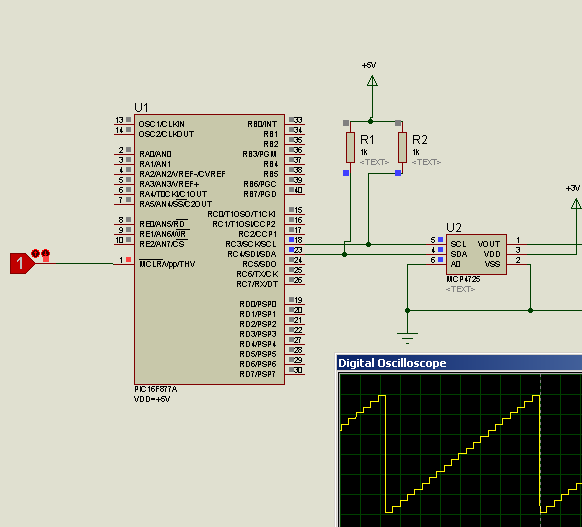
Hi all, this is MCP4725 DAC working example
| Code: | #use I2C(MASTER, scl=PIN_C3, sda=PIN_C4, FAST=400000 )
void dac_i2c(unsigned int16 sample){
i2c_start();
i2c_write(0b11000000); // Device address
i2c_write(0b1000000); // Internal Device address
i2c_write((sample & 0xFF0) >> 4); // Upper data bits (D11.D10.D9.D8.D7.D6.D5.D4)
i2c_write((sample & 0xF) << 4); //lower bits
i2c_stop(); // Stop
}
void main() {
unsigned long int i;
disable_interrupts(GLOBAL);
while(TRUE){
i+=200;
if(i>=4096) i=0;
dac_i2c(i);
}
} |
 |
|
 |
viki2000
Joined: 08 May 2013
Posts: 233
|
|
| Posted: Thu Jan 19, 2017 9:34 am |
|
|
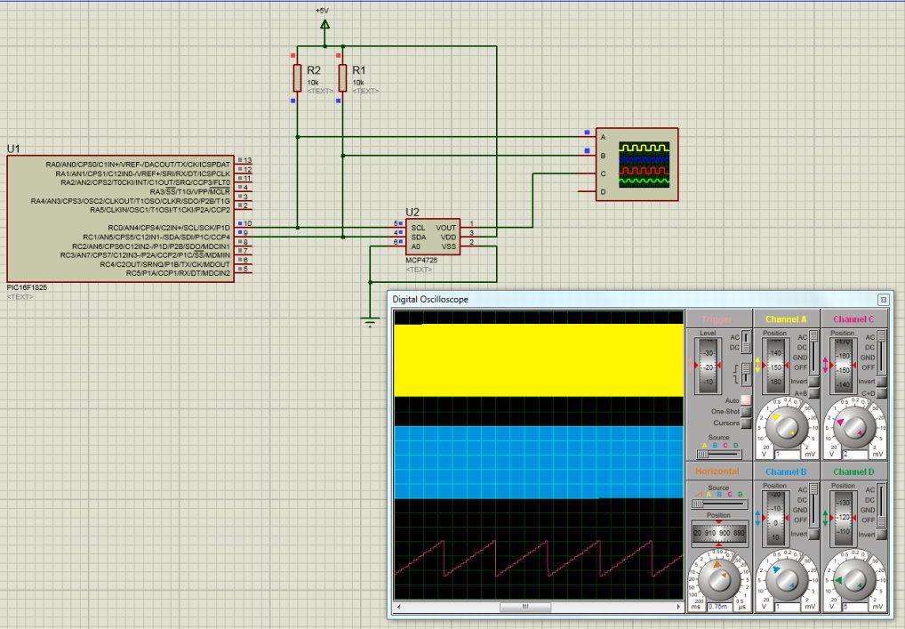
I have tried your example too and it works in simulation, but when I tried in reality with a real PIC and MCP4725, then it does not work.
I can see the I2C signals, even decode them with the oscilloscope and the problem is with Acknowledge.
Besides that on simulation and as well on real oscilloscope there is a strange pulse on SCL signal.
Did someone succeed with a real PIC and a real MCP4725?
 [/url] [/url]
 |
|
|
PCM programmer
Joined: 06 Sep 2003
Posts: 21708
|
|
| Posted: Thu Jan 19, 2017 11:15 am |
|
|
10K pullups are not appropriate for i2c Fast mode. Remove FAST from
the #use i2c() statement and see if it starts working.
If you want to run at 400 KHz, then change the pullups to 2.2K.
With a single i2c chip on the bus and if the chip is on the same circuit
board as the PIC, 2.2K should work. |
|
|
viki2000
Joined: 08 May 2013
Posts: 233
|
|
| Posted: Thu Jan 19, 2017 12:31 pm |
|
|
I will try that tomorrow.
Actually, today I have installed 1K pull up resistors and I have tried 400KHz and also 100KHz.
If it is of any help, I can post tomorrow screenshots from oscilloscope with I2C decoding. |
|
|
PCM programmer
Joined: 06 Sep 2003
Posts: 21708
|
|
| Posted: Thu Jan 19, 2017 7:21 pm |
|
|
1K actually violates the spec. About 1.6K is the smallest i2c pullup
resistor you should use in a 5v system. The MCP47
The webpage below has a block of 9 graphs, showing the waveforms
http://dsscircuits.com/articles/effects-of-varying-i2c-pull-up-resistors
for various pull-up resistor values. Your value of 10K has a curved
rising edge, while 2.2K or 1.5K is much better. |
|
|
viki2000
Joined: 08 May 2013
Posts: 233
|
|
|
viki2000
Joined: 08 May 2013
Posts: 233
|
|
| Posted: Fri Jan 20, 2017 2:45 am |
|
|
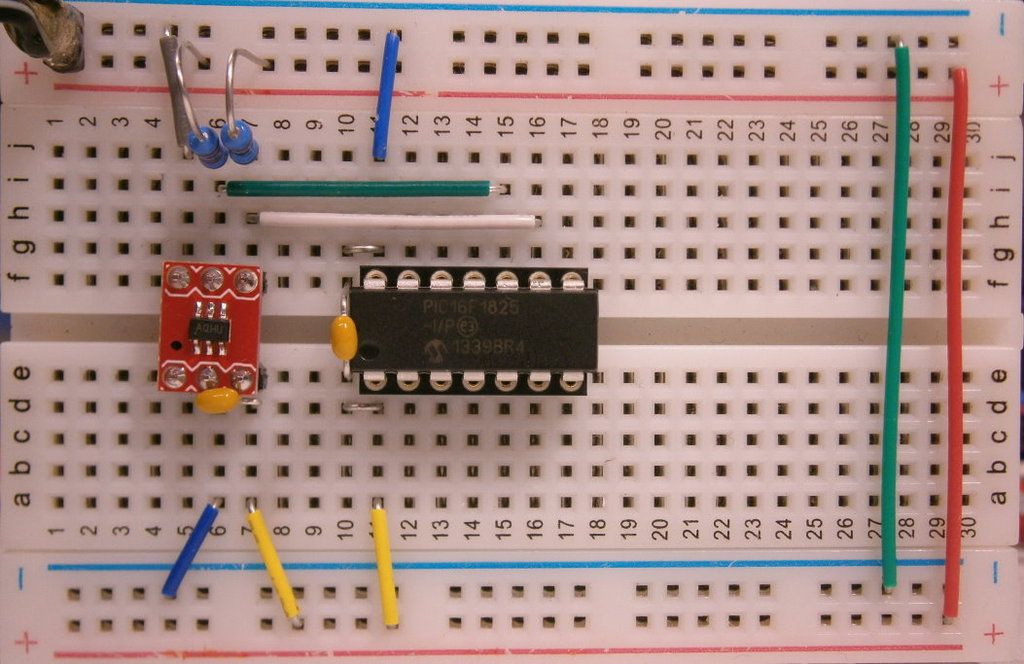
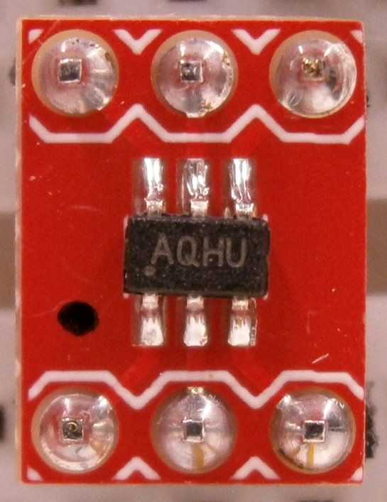
Here are some updates.
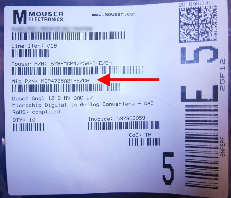
First of all I made some photos with the test breadboard that I use and that was the moment when I have seen the code on the MCP4725 and I double checked with its datasheet and surprise, the address on I2C is not A0, but A2, because the code is AQHU on the chip. Then I searched for the shipping bag from Mouser and was confirmed A2.
Then I changed in the code above the line:
i2c_write(0b11000000);
with the new address:
i2c_write(0b11000010);
Then I installed 2.2K pull up resistors and I removed the “FAST=400000” from #use line, as you suggested.
The MCP4725 still does not respond, the output voltage is a DC line 2.6-2.7V.
Because I have 10 such DACs, I tried with the 2nd one and the result was the same.
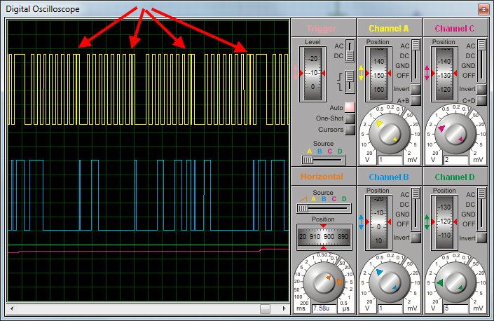
Then I watched the I2C signals and in the screenshots below, directly from real oscilloscope.
To make a stable reading on oscilloscope I replaced the dac_i2c(i); with a fixed, static value as dac_i2c(55);
The waveforms on SDA do not look as in Microchip PICtail board pdf page 16-17.
The problem seems related with Acknowledge bit.
 |
|
|
viki2000
Joined: 08 May 2013
Posts: 233
|
|
| Posted: Fri Jan 20, 2017 6:56 am |
|
|
I've got it running.
The error came from the address, which was confusing to be set.
I will come back Monday with explanations, details and oscilloscope screenshots. |
|
|
PCM programmer
Joined: 06 Sep 2003
Posts: 21708
|
|
| Posted: Fri Jan 20, 2017 9:51 am |
|
|
| Quote: | | The error came from the address. The address on I2C is not A0, but A2. |
I saw the other addresses in the data sheet but just assumed that the
factory shipped the A0 address as standard and that other addresses
were special order.
It's occured to me that I should have suggested running the i2c scanner
program. It would have found the slave address quickly.
http://www.ccsinfo.com/forum/viewtopic.php?t=49713 |
|
|
viki2000
Joined: 08 May 2013
Posts: 233
|
|
| Posted: Mon Jan 23, 2017 8:34 am |
|
|
Here are few explanations which may be useful for other users in future.
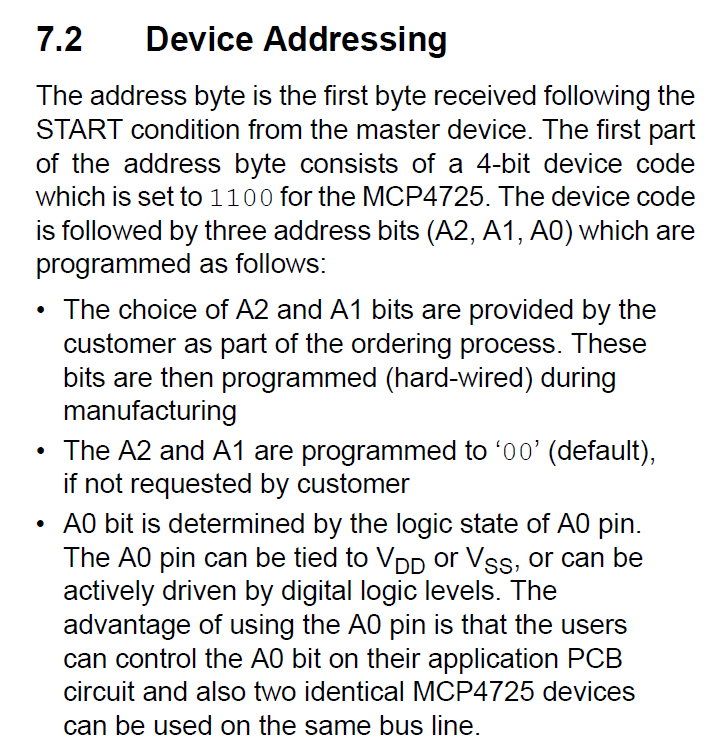
1)As I mentioned above, my 1st mistake was to not check the address of the real MCP4725, because on the datasheet at chapter 7.2 under Device addressing is written:
“The A2 and A1 are programmed to ‘00’ (default), if not requested by customer”
And I did not ask for any special address, so I asummed (wrong) that A2 and A1 is 00.
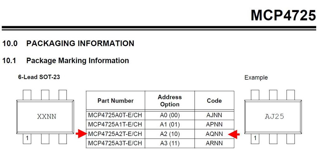
The code marking confirms the ordering code.
In my case A2 and A1 is 10, code marking starting with AQ.
2) When you look at the C code above any you check the device addressing how is it formed with A2, A1, A0, do not make the confusion/mistake with Address Option Part Number at Package Marking Information. There we have too A3, A2, A1, A0, but these have nothing to do with A2, A1, A0 used to form the I2C address. For me it created a small confusion. It would have been good if Microchip would use other names for Address Option Part Number at Package Marking Information.
3) When you write the C code you need the steps above.
You initialize once in the beginning the I2C.
Then each time when you send data from PIC to MCP4725 there are 6 steps in our case: START, SEND Device Address, SEND Internal Device Address, SEND DATA, SEND DATA, STOP.
4) The biggest nightmare that you might have is SEND Device Address if you do not know exactly what your address is. Probably using an I2C scanner would be easy as suggested.
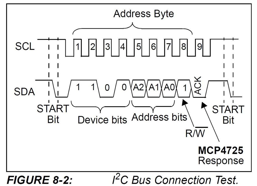
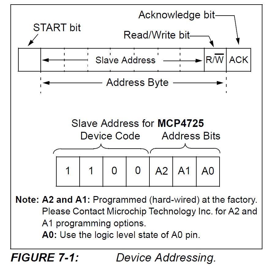
Looking in the datasheet of the MCP4725 we form the address as follows:
We start with 1100 for Device Code, then follows A2, A1, A0. In my case A2 and A1 is 10. A0 depends where is connected, to VSS it is 0 and to VDD is 1. In my case I connect to VSS(-) and I have the A0=0. Then I have Slave Address 1100 10 0. Here are 7bits. Because is a write operation, the last bit will be 0, which will be added after Slave Address to form the Address Byte. Then I got the Address Byte 11001000. This is what I will use in SEND Device Address.
5) Then follows SEND Internal Device Address.
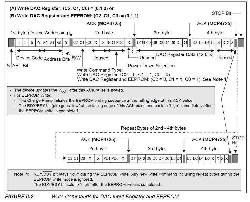
When we want to write only to MCP4735 register without writing to EPROM, then we have:
Write DAC Register: (C2, C1, C0) = (0,1,0).
Here we have C2 C1 C0 X X PD1 PD0 X, where X is unused, so we can consider 0. PD1 and PD0 bits are power down bits, which for normal operation are also 0. Only when we want to put MCP4725 in Sleep mode, low power consumption, then we modify these bits.
Then for normal operation, writing only to DAC register we have 010 00 00 0. This is what we send with SEND Internal Device Address.
6) The rest is data, sent in 2 lines, because the MCP4725 is 12bits, so we must split these 12 bits in 2, because we send 1byte (8bits) each time.
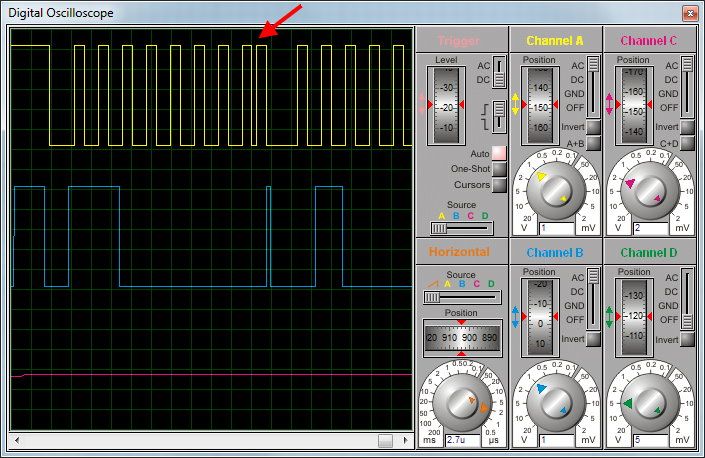
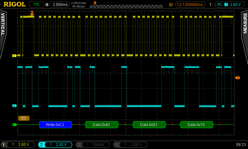
7) Below are the oscilloscope of a real working device, I2C signals and Output voltage.
First the output voltage:
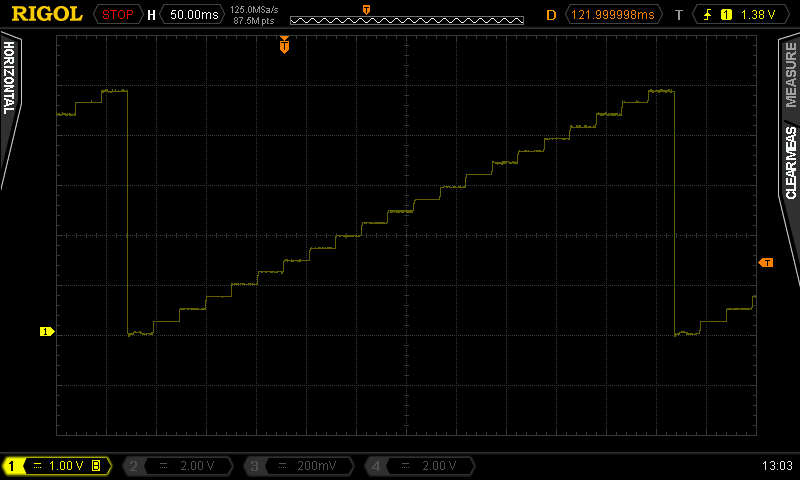
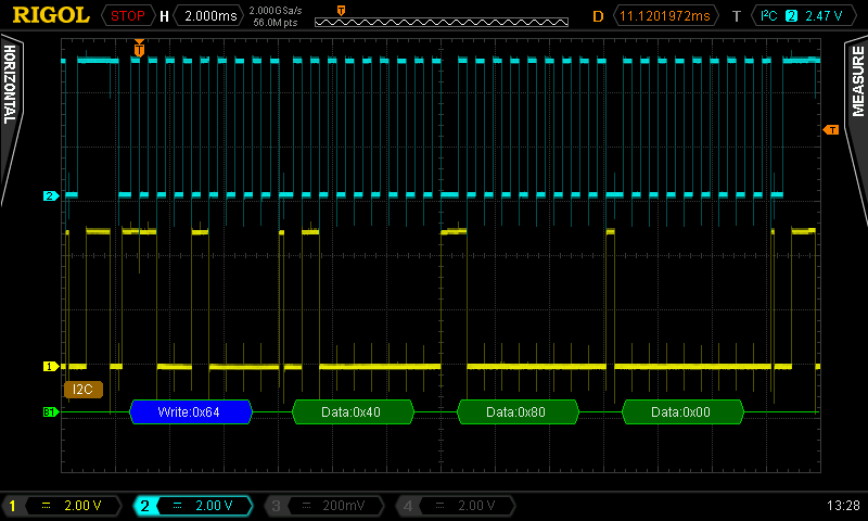
Then we have 4 bytes, the START and STOP is not decoded, but we can see it as signals. We have 0x64, 0x40, 0x80, 0x00. They correspond to writing decimal value 2048 to the DAC. We have like this:
a) 0x64 is hexadecimal for 11001000 – the SEND Device Address
b) 0x40 is hexadecimal for 01000000 – the SEND Internal Device Address
c) 0x80 is hexadecimal for 10000000 – the MSB bits of the 2048 decimal (0b100000000000)
d) 0x0 is hexadecimal for 00000000 – the LSB bits of the 2048 decimal (0b100000000000) |
|
|
viki2000
Joined: 08 May 2013
Posts: 233
|
|
| Posted: Tue Jan 24, 2017 5:08 am |
|
|
The code used for my tests is:
| Code: | #include <16F1825.h>
#fuses NOFCMEN, NOIESO, NOCLKOUT, BROWNOUT, NOCPD, NOPROTECT, NOMCLR, NOPUT, NOWDT, INTRC_IO
#fuses NOLVP, NODEBUG, BORV19, NOSTVREN, PLL, NOWRT
#use delay(clock=32M)
#use I2C(MASTER, scl=PIN_C0, sda=PIN_C1, FORCE_HW, FAST=400000)
void dac_i2c(unsigned int16 sample){
i2c_start(); // Start
i2c_write(0b11001000); // Device address
i2c_write(0b1000000); // Internal Device address
i2c_write((sample & 0xFF0) >> 4); // Upper data bits (D11.D10.D9.D8.D7.D6.D5.D4)
i2c_write((sample & 0xF) << 4); // Lower data bits (D3.D2.D1.D0)
i2c_stop(); // Stop
}
void main() {
setup_adc(ADC_OFF);
unsigned long int i=0;
disable_interrupts(GLOBAL);
while(TRUE){
i+=1;
if(i>=4096) i=0;
dac_i2c(i);
}
} |
At #use I2C parameters I tried without “FAST=400000” and then is the same as “FAST=100000”. Then I increased step by step the frequency and in my case worked up to 1.9MHz.
I have tested also “FORCE_SW” instead of “FORCE_HW” and takes a bit longer when I2C is emulated software, as expected, but is a very good option when the PIC does not have hardware I2C. |
|
|
viki2000
Joined: 08 May 2013
Posts: 233
|
|
| Posted: Tue Jan 24, 2017 6:16 am |
|
|
I would like to generate a rectified sinewave 1Vpp 100Hz using MCP4725 and lookup table.
The PIC is the same as above, PIC16F1825 working at 32MHz.
The values for lookup table we can generate either using next page:
http://www.daycounter.com/Calculators/Sine-Generator-Calculator.phtml
or, as I prefer, using next software Smart Sine:
http://tahmidmc.blogspot.de/2012/10/smart-sine-software-to-generate-sine.html
I used next code:
| Code: | #include <16F1825.h>
#fuses NOFCMEN, NOIESO, NOCLKOUT, BROWNOUT, NOCPD, NOPROTECT, NOMCLR, NOPUT, NOWDT, INTRC_IO
#fuses NOLVP, NODEBUG, BORV19, NOSTVREN, PLL, NOWRT
#use delay(clock=32M)
#use I2C(MASTER, scl=PIN_C0, sda=PIN_C1, FORCE_HW, FAST=600000)
CONST unsigned long SINE_WAVE[100] = {0, 26, 51, 77, 103, 128, 153, 179, 204, 228, 253, 277,
301, 325, 349, 372, 395, 417, 439, 460, 481, 502, 522, 542, 561, 579, 597, 614, 631, 647,
663, 677, 692, 705, 718, 730, 741, 752, 761, 771, 779, 786, 793, 799, 804, 809, 813, 815,
817, 819, 819, 819, 817, 815, 813, 809, 804, 799, 793, 786, 779, 771, 761, 752, 741, 730, 718,
705, 692, 677, 663, 647, 631, 614, 597, 579, 561, 542, 522, 502, 481, 460, 439, 417, 395, 372,
349, 325, 301, 277, 253, 228, 204, 179, 153, 128, 103, 77, 51, 26};
void dac_i2c(unsigned int16 sample){
i2c_start(); // Start
i2c_write(0b11001000); // Device address
i2c_write(0b1000000); // Internal Device address
i2c_write((sample & 0xFF0) >> 4); // Upper data bits (D11.D10.D9.D8.D7.D6.D5.D4)
i2c_write((sample & 0xF) << 4); // Lower data bits (D3.D2.D1.D0)
i2c_stop(); // Stop
}
void main() {
setup_adc(ADC_OFF);
unsigned long int i=0;
disable_interrupts(GLOBAL);
while(TRUE){
if (i++ == 99)
i = 0;
#asm
nop
nop
nop
nop
nop
nop
nop
nop
nop
nop
nop
nop
nop
nop
nop
nop
nop
nop
nop
nop
nop
nop
nop
nop
nop
nop
#endasm
dac_i2c(SINE_WAVE[i]);
}
} |
In order to achieve 100Hz I tweak the code in the next ways:
- Either I introduce some delays as “nop” above.
I have tried with “delay_us();” but is not so precise.
- Or I play with I2C bus speed.
In this case I set it to 600kHz.
- Both above, as I did it.
My problem is that I would like to emulate the sinewave as good as possible. That would imply more points in the lookup table. I have tried with 300 points and the I2C and the PIC is too slow.
Another idea would be to use instead of 5Vdc for PIC+DAC another voltage as 3Vdc for example.
The 1LSB of the DAC would be instead of 5V/4096 only 3V/4096 and I could get higher precision on Y axis, on amplitude. But that would not change my limitation on X axis, which is limited by the PIC code execution and I2C speed.
Do you have any thoughts on this, except using an SPI DAC that has higher speed than I2C DAC?
What about a simple PWM sinewave generator with lookup table (only the PIC PWM+ filter, without any DAC)? Would that generate a better sinewave, knowing that PWM has usually only 10bit resolution? |
|
|
|
|
You cannot post new topics in this forum
You cannot reply to topics in this forum
You cannot edit your posts in this forum
You cannot delete your posts in this forum
You cannot vote in polls in this forum
|
Powered by phpBB © 2001, 2005 phpBB Group
|

