| View previous topic :: View next topic |
| Author |
Message |
Bahadir A.
Joined: 19 Oct 2015
Posts: 6
Location: Antalya,Turkey


|
| AD7791 Driver |
 Posted: Mon Oct 19, 2015 1:01 pm Posted: Mon Oct 19, 2015 1:01 pm |
 |
|
Hello everyone.
I was following this gorgeous forum and today i have signed up 
In first place my English language is not very well, sorry
I am working on weigh scale project and my manager wants to use pic18f4550 and AD7791.
I have read datasheet AD7791 and i have created this library 
| Code: |
#define ADC_CS PIN_C3
#define ADC_SCLK PIN_C1
#define ADC_DIN PIN_C4
#define ADC_DOUT PIN_C5
void write_adc_byte(BYTE data);
void adc_reset()
{
BYTE i;
int16 rst=0xFFFF;
output_low(ADC_CS);
for(i=1;i<=32;++i) {
output_low(ADC_SCLK);
output_bit(ADC_DIN, shift_left(rst,4,1));
output_high(ADC_SCLK);
}
output_high(ADC_CS);
}
void write_adc_byte(BYTE data)
{
BYTE i;
output_low(ADC_CS);
delay_us(10);
for(i=1;i<=8;++i)
{
output_low(ADC_SCLK);
output_bit(ADC_DIN, shift_left(&data,1,0));
output_high(ADC_SCLK);
}
output_high(ADC_CS);
}
void adc_init()
{
output_high(ADC_SCLK);
output_high(ADC_CS); //Set low to AD7715 chip select low pin
adc_reset(); //Set high to AD7715 reset low pin
delay_ms(3000);
write_adc_byte(0x10); //Communications Register
write_adc_byte(0x82); //Data Register info here
}
int32 read_adc_word() {
BYTE i;
int32 data;
output_low(ADC_CS);
delay_us(10);
for(i=1;i<=24;++i) {
output_low(ADC_SCLK);
output_high(ADC_SCLK);
shift_left(&data,3,input(ADC_DOUT));
}
output_high(ADC_CS);
return data;
}
int32 read_adc_value() {
int32 value;
write_adc_byte(0x3C);
while ( input(ADC_DIN) )
while ( !input(ADC_DIN) )
while ( input(ADC_DIN) )
value=read_adc_word();
return value;
}
|
But i can't get any value with using this library. I would like Continous Read.
If someone help me, i'm really be grateful. |
|
 |
Ttelmah
Joined: 11 Mar 2010
Posts: 20005
|
|
| Posted: Mon Oct 19, 2015 1:31 pm |
|
|
To begin with, this is not going to work on your chip.
Always, when using a chip you _must_ look at the data sheet and know what pins are capable of doing. C4, and C5 on the 4550, are the USB pins. These can only be used as inputs, not outputs, so your DOUT pin is not actually going to work....
Now seriously, separately to this, for any speed what using SPI, you want to use the SPI _hardware_. Look at the CCS library #use spi, and use the hardware pins, then three quarters of the work (the sending and receiving of the actual bytes/words) is already done for you. The hardware will do this hundreds of times quicker than your software approach. |
|
|
Bahadir A.
Joined: 19 Oct 2015
Posts: 6
Location: Antalya,Turkey
|
|
| Posted: Mon Oct 19, 2015 11:19 pm |
|
|
Thank you so muck. I'll do what you said.
By the way I'm so sorry. Chip is not Pic18f4550 , my chip is PIC18F45K80. |
|
|
PCM programmer
Joined: 06 Sep 2003
Posts: 21708
|
|
| Posted: Tue Oct 20, 2015 2:19 pm |
|
|
What is this ?
| Quote: | int32 read_adc_value() {
int32 value;
write_adc_byte(0x3C);
while ( input(ADC_DIN) )
while ( !input(ADC_DIN) )
while ( input(ADC_DIN) )
value=read_adc_word();
return value;
}
|
I think you copied the code from the CCS driver file ad7715.c, but
notice how they have a semi-colon at the end of each line:
| Code: |
long int read_adc_value() {
long int value;
while ( input(ADC_DRDY) ); // Wait until DRDY goes low
while ( !input(ADC_DRDY) ); // Then wait until it goes high
while ( input(ADC_DRDY) ); // Then wait for it to go low
write_adc_byte(0x3a);
value=read_adc_word();
return value;
}
|
|
|
|
Bahadir A.
Joined: 19 Oct 2015
Posts: 6
Location: Antalya,Turkey
|
|
| Posted: Tue Oct 20, 2015 11:42 pm |
|
|
Yes, i wrote this driver inspired by 7715 driver.
We changed this sector, because we getting always 0x00FFFFFF or 0x00 result :(. (either have a semi-colon or not )
| Code: |
while ( input(ADC_DIN) )
while ( !input(ADC_DIN) )
while ( input(ADC_DIN) )
|
We changed driver software as a following type. But still there is no output value without 0x00FFFFFF or 0x00 :(.
| Code: |
#define ADC_CS PIN_C3
#define ADC_SCLK PIN_C1
#define ADC_DIN PIN_C4
#define ADC_DOUT PIN_C5
void write_adc_byte(BYTE data);
//-------------------------------------------------------------------
void adc_reset()
{
BYTE i;
int16 rst=0xFFFF;
output_low(ADC_CS);
delay_us(1);
for(i=0;i<32;++i)
{
output_low(ADC_SCLK);
delay_us(1);
output_bit(ADC_DIN, bit_test(&rst,31-i));
output_high(ADC_SCLK);
delay_us(1);
}
delay_us(1);
output_high(ADC_CS);
}
//-------------------------------------------------------------------
void write_adc_byte(BYTE data)
{
BYTE i;
output_low(ADC_CS);
delay_us(10);
for(i=0;i<8;++i)
{
output_low(ADC_SCLK);
delay_us(1);
output_bit(ADC_DIN, bit_test(&data,7-i));
output_high(ADC_SCLK);
delay_us(1);
}
delay_us(10);
output_high(ADC_CS);
}
//-------------------------------------------------------------------
void adc_init()
{
output_high(ADC_SCLK);
output_high(ADC_CS); //Set low to AD7715 chip select low pin
adc_reset(); //Set high to AD7715 reset low pin
delay_ms(1000);
}
//--------------------------------------Aşağısı Kontrol Edilecek---------------------//
int32 read_adc_word()
{
BYTE i;
int32 rdata;
rdata = 0;
output_low(ADC_CS);
delay_us(10);
for(i=1;i<=24;++i) {
output_low(ADC_SCLK);
delay_us(1);
output_high(ADC_SCLK);
delay_us(1);
shift_left(&rdata,3,input(ADC_DOUT));
}
output_high(ADC_CS);
return rdata;
}
//-------------------------------------------------------------------
int32 read_adc_value() {
int32 value;
write_adc_byte(0x10);
write_adc_byte(0x82);
// while ( input(ADC_DOUT) );
// while (!input(ADC_DOUT) );
// while ( input(ADC_DOUT) );
value=read_adc_word();
return value;
}
|
|
|
|
PCM programmer
Joined: 06 Sep 2003
Posts: 21708
|
|
| Posted: Wed Oct 21, 2015 5:19 am |
|
|
| Quote: | We changed driver software as a following type. But still there is no output value without 0x00FFFFFF or 0x00 :(.
#define ADC_CS PIN_C3
#define ADC_SCLK PIN_C1
#define ADC_DIN PIN_C4
#define ADC_DOUT PIN_C5 |
Post your list of connections between the PIC and the AD7791.
For example, what pin on the AD7791 is connected to Pin C4 on the PIC ?
Etc. Check the connections with an ohmmeter and post the list.
Also, what do you have connected to the other pins on the AD7791,
such as REFIN+ and REFIN-, AIN+ and AIN-, and Vdd and Vss ? |
|
|
Bahadir A.
Joined: 19 Oct 2015
Posts: 6
Location: Antalya,Turkey
|
|
| Posted: Wed Oct 21, 2015 6:06 am |
|
|
My chip is PIC18F45K80
All the connection is that.
AD7791 Pins;
10.Pin(DIN) to (Pin_C4) PIC 42.Pin
9.Pin(DOUT/RDY) to (Pin_C5) PIC 43.Pin
1.Pin(SCLK) to (Pin_C1)PIC 35.Pin
2.Pin(CS) to (Pin_C3)PIC 37.Pin
3.Pin AIN+
4.Pin AIN-
5.Pin Ref+
6.Pin Ref-
7.Pin Gnd
8.Pin Vdd |
|
|
PCM programmer
Joined: 06 Sep 2003
Posts: 21708
|
|
| Posted: Wed Oct 21, 2015 6:35 am |
|
|
The top 4 connections look OK, but do you really have no connections to
these pins below ?
| Quote: |
3.Pin AIN+
4.Pin AIN-
5.Pin Ref+
6.Pin Ref-
7.Pin Gnd
8.Pin Vdd |
Surely you must have at least power and ground. Post the true
connections to the above pins.
The AD7791 data sheet says:
| Quote: | A write operation of at least 32 serial clock cycles with DIN high
returns the ADC to this default state by resetting the entire part. |
But in the code below, 'rst' is an int16 set to 0xFFFF, so you are only
sending 16 1's. 'rst' should be an int32 and it should be set to 0xFFFFFFFF.
| Quote: | void adc_reset()
{
BYTE i;
int16 rst=0xFFFF;
output_low(ADC_CS);
delay_us(1);
for(i=0;i<32;++i)
{
output_low(ADC_SCLK);
delay_us(1);
output_bit(ADC_DIN, bit_test(&rst,31-i));
output_high(ADC_SCLK);
delay_us(1);
}
delay_us(1);
output_high(ADC_CS);
} |
|
|
|
Bahadir A.
Joined: 19 Oct 2015
Posts: 6
Location: Antalya,Turkey
|
|
| Posted: Wed Oct 21, 2015 7:01 am |
|
|
3.Pin AIN+
4.Pin AIN-
5.Pin Ref+
6.Pin Ref-
7.Pin Gnd
8.Pin Vdd
Ref+ and Ref- pins are connected to Load Cell directly.
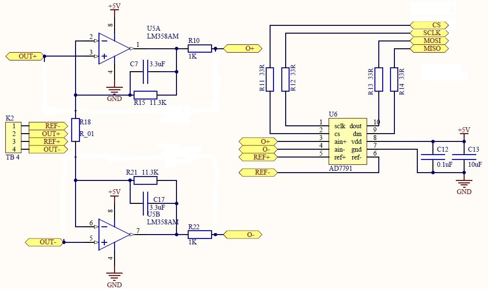
AIN+ and AIN- pins are connected to Load Cell indirectly. There is a 8667 opamp ic. between Load Cell's AIN- and AIN+ pins and AD7791's AIN-&AIN+ pins.Scheme at below. (DIN and DOUT is inverse at scheme but we crossed it and we used 8667 instead of LM358)
I did what your said. Rst=0xFFFFFFFF now.
However in debugger mode i progressed step by step, i could get a result even though irrelevant :(.
But when i push run on mplab ide , i got 0x00FFFFFF again :(. |
|
|
PCM programmer
Joined: 06 Sep 2003
Posts: 21708
|
|
| Posted: Wed Oct 21, 2015 8:45 am |
|
|
I noticed another thing about your code. You are continuously dropping
and raising Chip Select. In the timing diagrams in the AD7791 data sheet
(pages 16 and 17), they drop CS at the start of transaction, and keep it
low for the duration of the transaction. They don't cycle CS when sending
command bytes.
The AD7791 data sheet says:
| Quote: | Continuous Conversion Mode
If CS is low, the DOUT/RDY line will also go low when a conversion is complete. |
That explains why the DOUT polling section (below) never worked.
You don't have CS low. It's only low in the write_adc_byte() routine.
When you start to poll DOUT, CS is high, and it won't be able to read DOUT.
| Code: |
int32 read_adc_value() {
int32 value;
write_adc_byte(0x10);
write_adc_byte(0x82);
// while ( input(ADC_DOUT) );
// while (!input(ADC_DOUT) );
// while ( input(ADC_DOUT) );
value=read_adc_word();
return value;
} |
Also, I don't think you need 3 lines of polling various levels. According
to Figure 15 (Continuous Read), you send the 0x3C command, then you
poll DOUT and wait until it goes low. So you could accomplish the polling
with only this line:
| Code: | | while ( input(ADC_DOUT) ); |
With that line, the program will stay in the while() loop as long as the
DOUT line is high. When DOUT goes low, the code will break out of that loop.
That's what you want.
I think you need to re-write your code so it does the transaction exactly
as shown in Figure 15. It must keep CS low during the entire transaction. |
|
|
|


