| View previous topic :: View next topic |
| Author |
Message |
edhaslam
Joined: 15 Jul 2005
Posts: 89
Location: UK


|
| Which FET? |
 Posted: Wed Apr 09, 2008 8:20 am Posted: Wed Apr 09, 2008 8:20 am |
 |
|
As power electronics is not really my speciality I thought I'd post here for some advice!
I'm designing a remotely operated pumping system. Basically I need to switch on two different pumps and I was planning on using a separate FET for each. Each pump is rated at +24V @ 2.5A (max) and has it's own power supply.
I've tried using a BUZ11 who's gate is connected directly to a PIC18F6722 port pin, with a 100k resistor pulling it low. When I pull the pin high, either the FET doesn't switch on or the pump runs very slowly. Could this be because the BUZ11 requires more than 5V to switch on?
I've had a look at some other FETs (IRL1004) so I might give those a try... |
|
 |
Matro
Guest
|
|
| Posted: Wed Apr 09, 2008 8:27 am |
|
|
It should work but it depends on the length of cable that you have between each part.
But this MOSFET is definitely not appropriate for that.
I will look if I find something appropriate for that.
A good deal will be a 20/25/30 V and 5/10/12 A MOSFET.
It could be even better if it is commanded through a NPN transistor or another N-MOS.
Matro. |
|
|
Matro
Guest
|
|
| Posted: Wed Apr 09, 2008 8:33 am |
|
|
The voltage I gave previously was Vgs and not Vds. ;-)
This reference from Vishay seems perfect : "SUU50N04-25P".
This is not the only one but the first I found.
I look only for THD since you didn't say if SMD was acceptable.
Matro. |
|
|
newguy
Joined: 24 Jun 2004
Posts: 1908
|
|
| Posted: Wed Apr 09, 2008 9:04 am |
|
|
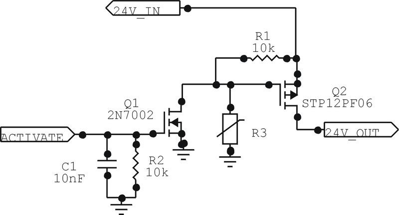
This circuit layout will work. I have this same system (with some parts removed/hidden) working in an automotive environment. The main p-channel FET is rated for 60V and 12A, and its Digikey part number is 497-2721-5-ND. R3 is an MOV. For your application it should be rated for ~30V. It would also be a good idea to place a series resettable fuse inline between the FET and your pump. Another MOV to ground at that point would help to protect everything.
Edit: p-channel FET symbol fixed.
Last edited by newguy on Wed Apr 09, 2008 9:39 am; edited 1 time in total |
|
|
Matro
Guest
|
|
| Posted: Wed Apr 09, 2008 9:18 am |
|
|
| newguy wrote: |
This circuit layout will work. I have this same system (with some parts removed/hidden) working in an automotive environment. The main p-channel FET is rated for 60V and 12A, and its Digikey part number is 497-2721-5-ND. R3 is an MOV. For your application it should be rated for ~30V. It would also be a good idea to place a series resettable fuse inline between the FET and your pump. Another MOV to ground at that point would help to protect everything. |
The schematic as a bug.
Q2 is a P-channel (what is correct) but the symbol is the one of an N-channel MOSFET. ;-)
Matro. |
|
|
SherpaDoug
Joined: 07 Sep 2003
Posts: 1640
Location: Cape Cod Mass USA
|
| Re: Which FET? |
| Posted: Wed Apr 09, 2008 11:58 am |
|
|
| edhaslam wrote: |
I've tried using a BUZ11 who's gate is connected directly to a PIC18F6722 port pin, with a 100k resistor pulling it low. When I pull the pin high, either the FET doesn't switch on or the pump runs very slowly. Could this be because the BUZ11 requires more than 5V to switch on?
|
The supplied schematic will almost work (see below), but you may want to know why your original idea won't. The problem is that the BUZ11 needs 5V (or better yet 12V) from Gate to Source. If you connect the drain to your +24V supply and the source to the pump motor, and the other side of the pump motor to ground, then the PIC raises the gate to 5V vs ground. The FET turns on and starts supplying power to the pump. This causes the pump voltage to rise which raises the FET source voltage towards the gate voltage, shutting off the FET. It soon reaches equilibrium where the FET gate to source voltage and the pump voltage are both starved, the pump runs slowly and the FET gets hot. This is a "source follower" circuit which is useful for some analog work, but makes a poor switch.
_________________
The search for better is endless. Instead simply find very good and get the job done.
Last edited by SherpaDoug on Wed Apr 09, 2008 1:04 pm; edited 2 times in total |
|
|
SherpaDoug
Joined: 07 Sep 2003
Posts: 1640
Location: Cape Cod Mass USA
|
|
| Posted: Wed Apr 09, 2008 12:12 pm |
|
|
There is another problem with the schematic. The max allowable voltage from gate to source of Q2 is 20V. When Q1 turns on it pulls Q2 gate to near GND while Q2 source is still at 24V. This may work for a while but will eventually blow the gate insulation of Q2. You need to add another 10k resistor between R1 and Q1 to drop the Q2 gate drive to a safe level.
This is a common error which results in a lot of delayed failures and product recalls.
_________________
The search for better is endless. Instead simply find very good and get the job done. |
|
|
newguy
Joined: 24 Jun 2004
Posts: 1908
|
|
| Posted: Wed Apr 09, 2008 1:07 pm |
|
|
| SherpaDoug wrote: | There is another problem with the schematic. The max allowable voltage from gate to source of Q2 is 20V. When Q1 turns on it pulls Q2 gate to near GND while Q2 source is still at 24V. This may work for a while but will eventually blow the gate insulation of Q2. You need to add another 10k resistor between R1 and Q1 to drop the Q2 gate drive to a safe level.
This is a common error which results in a lot of delayed failures and product recalls. |
Nice one. I use this on a 12V automotive system with (obviously) no issues since I'm not near the 20V limit. I didn't reexamine the data sheet for the transistor when I posted the schematic. I guess I should have. Oh well, it's an easy fix - just find another p channel FET with ratings suitable for the 24V case. |
|
|
Matro
Guest
|
|
| Posted: Wed Apr 09, 2008 1:55 pm |
|
|
| newguy wrote: | | SherpaDoug wrote: | There is another problem with the schematic. The max allowable voltage from gate to source of Q2 is 20V. When Q1 turns on it pulls Q2 gate to near GND while Q2 source is still at 24V. This may work for a while but will eventually blow the gate insulation of Q2. You need to add another 10k resistor between R1 and Q1 to drop the Q2 gate drive to a safe level.
This is a common error which results in a lot of delayed failures and product recalls. |
Nice one. I use this on a 12V automotive system with (obviously) no issues since I'm not near the 20V limit. I didn't reexamine the data sheet for the transistor when I posted the schematic. I guess I should have. Oh well, it's an easy fix - just find another p channel FET with ratings suitable for the 24V case. |
An automotive system should be able to withstand a continous 24V power supply, 36V during 1 min, and 100V spikes...
So the FET you've chosen seems not completely appropriate for automotive electronics.
Matro. |
|
|
w2drz
Joined: 27 Dec 2006
Posts: 55
Location: Western New York - USA

|
| HEX FET is another device to use |
| Posted: Wed Apr 09, 2008 2:31 pm |
|
|
Hi,
This is for a HEX FET circuit,
as it is both P and N channel circuit use pieces as need.
MFR is:
http://www.irf.com/indexsw.html
One issue driviing a inductor is back EMF voltage when switched off.
Most IR hexfet has built in diode supression for this condition when switched off.
Note the use of 10 volt zenier (1N5240) in gate circuit and a driver transistor,
as your circuit may exceed the PICC pin voltage rating with out a driver transistor that may be needed also.
The device in example is good for 74 amps, there are others in the series better for the lower current you describe.
Example of circuit and use is:
http://www.w2drz.ramcoinc.com/HexFet.htm
tom W2DRZ |
|
|
newguy
Joined: 24 Jun 2004
Posts: 1908
|
|
| Posted: Wed Apr 09, 2008 3:56 pm |
|
|
| Matro wrote: | An automotive system should be able to withstand a continous 24V power supply, 36V during 1 min, and 100V spikes...
So the FET you've chosen seems not completely appropriate for automotive electronics. |
24V continuous? How? The highest vehicle voltage I've ever measured was 18V when something in my alternator failed.
The automotive device I mentioned has been running for over 2 years now and has even withstood a direct hit from an arc welder with only a damaged connector to show for it. I honestly can't see how a normal 12V frame ground automotive environment "must" be designed to withstand 24V continuous. This isn't for a semi (they're 24V, aren't they?). |
|
|
ak6dn
Joined: 08 Jan 2006
Posts: 23
Location: Saratoga, CA USA
|
| Re: Which FET? |
| Posted: Wed Apr 09, 2008 10:02 pm |
|
|
| edhaslam wrote: | As power electronics is not really my speciality I thought I'd post here for some advice!
I'm designing a remotely operated pumping system. Basically I need to switch on two different pumps and I was planning on using a separate FET for each. Each pump is rated at +24V @ 2.5A (max) and has it's own power supply.
I've tried using a BUZ11 who's gate is connected directly to a PIC18F6722 port pin, with a 100k resistor pulling it low. When I pull the pin high, either the FET doesn't switch on or the pump runs very slowly. Could this be because the BUZ11 requires more than 5V to switch on?
I've had a look at some other FETs (IRL1004) so I might give those a try... |
The BUZ11 has a Vgs(th) of 2-4V, so a 5V PIC output can turn it on fully no problem. Rds(on) is 30mOhm, Id(max) is 30A so it should easily handle your pumps. Vgs(max) is +/-20V and Vds(max) is 50V so it will work with your 24V supply and the 5V PIC output.
The key point is the source of the FET *must* be at 0V (ground) potential for it to work in this application. The +24V supply must go to the pump, and the return lead from the pump must connect to the drain of the FET. You end up with the switch in the return leg of the pump.
This circuit will NOT work switching the positive leg of the pump supply where +24V connects to the FET drain, and the FET source connects to the pump, and the pump return is grounded.
Don |
|
|
Matro
Guest
|
|
| Posted: Thu Apr 10, 2008 1:23 am |
|
|
| newguy wrote: | | Matro wrote: | An automotive system should be able to withstand a continous 24V power supply, 36V during 1 min, and 100V spikes...
So the FET you've chosen seems not completely appropriate for automotive electronics. |
24V continuous? How? The highest vehicle voltage I've ever measured was 18V when something in my alternator failed.
The automotive device I mentioned has been running for over 2 years now and has even withstood a direct hit from an arc welder with only a damaged connector to show for it. I honestly can't see how a normal 12V frame ground automotive environment "must" be designed to withstand 24V continuous. This isn't for a semi (they're 24V, aren't they?). |
Yes, they are. ;-)
I just wrote what are the specifications required for a so-called "automotive" system. Just for everybody's information. ;-)
Matro. |
|
|
edhaslam
Joined: 15 Jul 2005
Posts: 89
Location: UK
|
|
| Posted: Thu Apr 10, 2008 3:16 am |
|
|
Newguy> Many thanks for sharing your circuit with us, it seems ideal with the modifications that have been suggested for my application.
SherpaDoug> Thank you for your explanation of why my circuit wasn't working. I've learnt something there at least!
Thanks to everyone else for their comments...
| newguy wrote: | | Oh well, it's an easy fix - just find another p channel FET with ratings suitable for the 24V case. |
Just having a look for one now - can anyone suggest a suitable device?
|
|
|
Guest
|
|
| Posted: Thu Apr 10, 2008 5:58 am |
|
|
Why not just use a logic level high side switch like the IRF511 type devices?
Basically bullit proof,5A load,easy to interface,ONE part does it all.Yes it night cost a bit more up front, but factor in R&D time,etc and it's actually cheaper int he long run.
Jay |
|
|
|


