| View previous topic :: View next topic |
| Author |
Message |
anestho
Joined: 27 Dec 2006
Posts: 28


|
| 50 Hz software PWM for servos |
 Posted: Sun Jul 08, 2007 7:25 pm Posted: Sun Jul 08, 2007 7:25 pm |
 |
|
PCMProgrammer posted this code a while ago.
| Code: | #include <16F877.H>
#fuses XT, NOWDT, NOPROTECT, BROWNOUT, PUT, NOLVP
#use delay(clock = 4000000)
#define PWM_PIN PIN_B1
#define LOOPCNT 39
int8 width;
//-------------------------------
#INT_RTCC
void tick_interrupt(void);
//====================================
main()
{
width = 10;
setup_counters(RTCC_INTERNAL, RTCC_DIV_1);
enable_interrupts(INT_RTCC);
enable_interrupts(GLOBAL);
while(1);
}
//====================================
#INT_RTCC
void tick_interrupt(void)
{
static int8 loop = LOOPCNT;
static int8 pulse;
if(--loop == 0)
{
loop = LOOPCNT;
pulse = width;
}
if(pulse)
{
output_high(PWM_PIN);
pulse--;
}
else
{
output_low(PWM_PIN);
}
} |
I realize the above code is for 100 Hz, but it can be changed to 50 Hz by increasing clock speed to 8 Mhz from 4 Mhz (or making LOOPCNT = 39/2)
At 8 Mhz, the RTCC would then run at 0.5 us / tick and with 1:2 prescaling would be 1 us/tick x 256 ticks for the RTCC rollover x 78 = 19968 us or about 20 ms period.
A servo requires a 5% to 10% duty cycle at 50Hz or 20 ms. That means that the servo responds to 1 ms (5% duty) to 2ms (10% duty).
I may be missing something, but it seems that the resolution of the above code is very low (with the above changes). With width = 4 (5% duty) to width = 8 (10% duty). Is there a better way to increase the resolution to say 8 bit (0-255) to account for the 5% to 10% duty cycle without using delays to form the period?
I can preload timer0 with -32 to get 32 us x 625 = 20,000 us period, but even this only leaves 31 step resolution.
I am using a pic 12F683 at 8 Mhz internal osc. |
|
 |
anestho
Joined: 27 Dec 2006
Posts: 28
|
|
| Posted: Sun Jul 08, 2007 7:34 pm |
|
|
| I am using timer1 for something else, so it seems I can't use the CCP compare method of generating the signal. |
|
|
inservi
Joined: 13 May 2007
Posts: 128
|
|
| Posted: Mon Jul 09, 2007 10:14 am |
|
|
Hello,
you can use timer 2 with this setup :
setup_timer_2(T2_DIV_BY_1,7,1);
So you have 4 uSec resolution or 250 step by ms.
change :
#use delay(clock = 4000000) by #use delay(clock = 8000000)
#define LOOPCNT 5000
change #INT_RTCC by #int_TIMER2
change enable_interrupts(INT_RTCC); by enable_interrupts(INT_TIMER2);
change int8 width; by int16 width;
width = between 251 (for 1ms) and 501 (for 2 ms)
change static int8 loop = LOOPCNT; by static int16 loop = LOOPCNT;
change static int8 pulse; by static int16 pulse;
I hope that can help you.
I have not tested but i think that you can optimize the "tick_interrupt" function.
| Code: |
//====================================
#int_TIMER2
void tick_interrupt(void)
{
static int16 loop = LOOPCNT;
static int16 pulse;
if(--loop == 0) {
loop = LOOPCNT;
pulse = width;
output_high(PWM_PIN);
}
if(pulse) {
if (--pulse == 0) output_low(PWM_PIN);
}
} |
So the output_high(PWM_PIN); and output_low(PWM_PIN); are executing only when it is necessary.
It is one very special moment for me. It is the first time that I can propose an improvement for the always excellent code of PCMProgrammer.
dro.
here is the (not tested code) | Code: | #include <16F877>
#fuses XT, NOWDT, NOPROTECT, BROWNOUT, PUT, NOLVP
#use delay(clock = 8000000)
#define PWM_PIN PIN_B1
#define LOOPCNT 5000
int16 width;
//-------------------------------
#int_TIMER2
void tick_interrupt(void);
//====================================
main()
{
width = 377; // for 1.5ms)
setup_timer_2(T2_DIV_BY_1,7,1);
enable_interrupts(INT_TIMER2);
enable_interrupts(GLOBAL);
while(1);
}
//====================================
#int_TIMER2
void tick_interrupt(void) {
static int16 loop = LOOPCNT;
static int16 pulse;
if(--loop == 0) {
loop = LOOPCNT;
pulse = width;
output_high(PWM_PIN);
}
if(pulse) {
if (--pulse == 0) output_low(PWM_PIN);
}
} |
_________________
in médio virtus |
|
|
Guest
|
|
| Posted: Mon Jul 09, 2007 12:12 pm |
|
|
Thank you  I'm just concerned that 4 us per interrupt may be to short. Does it not take say 40 instructions to get in and get out of the interrupt. 1 instruction = 4 clock cycles = 0.5 us x 4 = 2 us .. I could not get interrupts to work less than say 32 us per interrupt. I'm just concerned that 4 us per interrupt may be to short. Does it not take say 40 instructions to get in and get out of the interrupt. 1 instruction = 4 clock cycles = 0.5 us x 4 = 2 us .. I could not get interrupts to work less than say 32 us per interrupt.
Have you tried interrupts with 4 us? |
|
|
PCM programmer
Joined: 06 Sep 2003
Posts: 21708
|
|
| Posted: Mon Jul 09, 2007 12:20 pm |
|
|
| Quote: | | Does it not take say 40 instructions to get in and get out of the interrupt |
It sure does. |
|
|
inservi
Joined: 13 May 2007
Posts: 128
|
|
| Posted: Mon Jul 09, 2007 12:23 pm |
|
|
Hello,
I have not tested but your right !
I just take an example without calculate limits. You need to give some precision about your goal.
What resolution do you need ?
What is the maximum clock you can use ?
but i think that the idea to use the "PCM programmer"'s code with some litle changes is good.
dro.
_________________
in médio virtus |
|
|
Guest
|
|
| Posted: Tue Jul 10, 2007 7:34 am |
|
|
| I would like 8 bit resolution with an 8Mhz clock (internal). I am using timer1 to count the length of the RC pulses from the pulse train. I could use another timer, but I would have to /16 to get it into the 0-255 range, since timer0 and 2 are both 8 bit. |
|
|
anestho
Joined: 27 Dec 2006
Posts: 28
|
|
| Posted: Tue Jul 10, 2007 11:16 am |
|
|
I thought about it in another way. I am planning on using 2 interrupts. Timer2 would be set to rollover every 20 ms. In the interrupt, I will load timer 0 with a value 127-255 and turn on pin 5.
Timer 0 interrupt will be prescaled 1:16 which at 8 Mhz is 8 us per tick.
in the interrupt, I will turn pin 5 off.
A loading a value of 127 would take (127 x 8)~ 1ms and a value of 0 would take (255 x 8) ~ 2 ms
Does this sound reasonable? |
|
|
inservi
Joined: 13 May 2007
Posts: 128
|
|
| Posted: Wed Jul 11, 2007 10:03 am |
|
|
Hello,
That look to be a good idea!
dro.
_________________
in médio virtus |
|
|
windz
Joined: 19 Aug 2007
Posts: 7
|
|
| Posted: Wed Sep 05, 2007 9:58 pm |
|
|
-PIC16F877a
-controlling Hitec HS-81MG RC servo motor
-CCS V4.049
Hi all, From the original code by PCM PROGRAMMER, i would like to know
1)How do you configure the code to be able to change the PULSE PERIOD and PULSE WIDTH ?? What does LOOPCNT refers to ? I've read the CCSC.pdf, but i can't find it.
2)My purpose is to drive a RC servo, with 1ms, 1.5ms, and 2ms position.
| Code: | #include <16F877.H>
#fuses XT, NOWDT, NOPROTECT, BROWNOUT, PUT, NOLVP
#use delay(clock = 20000000)
#define PWM_PIN PIN_B1
#define LOOPCNT 39
int8 width;
//-------------------------------
#INT_RTCC
void tick_interrupt(void);
//====================================
main()
{
width = 10;
setup_counters(RTCC_INTERNAL, RTCC_DIV_2);
enable_interrupts(INT_RTCC);
enable_interrupts(GLOBAL);
while(1);
}
//====================================
#INT_RTCC
void tick_interrupt(void)
{
static int8 loop = LOOPCNT;
static int8 pulse;
if(--loop == 0)
{
loop = LOOPCNT;
pulse = width;
}
if(pulse)
{
output_high(PWM_PIN);
pulse--;
}
else
{
output_low(PWM_PIN);
}
} |
This is what i get from oscilloscope
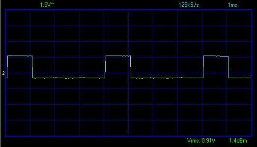
and the readings:
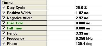
I have done a simple driver to run the servo motor, but i think using interrupt might be a better solutions, so i am learning how to use interrupt to drive the servo motor. Can anyone out there help me pls ?
for different position, i just change the delay. It's not a good program right? Trying to learn interrupt and use PIC PWM to control the servo, any helps would be very much appreciated.
| Code: | #use delay(clock = 20000000)
#define PWM1_PIN PIN_B1
//-----------servo at 1ms--------------------------
int8 i;
void servo1ms(){
for(i=0; i<30; i++){ //loops vary on application needs
output_high(PWM1_PIN); //position at 1ms
delay_ms(1);
output_low(PWM1_PIN);
delay_ms(19);
delay_ms(5);
}
}
|
|
|
|
PCM programmer
Joined: 06 Sep 2003
Posts: 21708
|
|
|
|


