 |
 |
| View previous topic :: View next topic |
| Author |
Message |
Stepper
Guest
|
| Stepper motor from printer and drive it |
 Posted: Sun Mar 27, 2005 5:20 am Posted: Sun Mar 27, 2005 5:20 am |
 |
|
I have Unipolar Stepper Motor from printer and driver to it LB1845
I run it by 1/4 step mode
And I need function to drive it in both direction.
Maybe someone can help me
| Code: |
#BYTE PORTC=0xf82
#BIT i11=PORTC.0 //i11
#BIT en0=PORTC.1 //enable
#BIT en1=PORTC.2 //enable
#BIT Ph1=PORTC.3 //phase
#BIT Ph2=PORTC.4 //phase
#BIT i02=PORTC.5 //i02
#BIT i12=PORTC.6 //i12
#BIT i01=PORTC.7 //i01
void position(int8 pos) // as in datasheet
{
switch (pos)
{
case 0: { ph1=0; i11=0; i01=0; ph2=1; i12=1; i02=1; break;}
case 1: { ph1=0; i11=0; i01=0; ph2=0; i12=1; i02=0; break;}
case 2: { ph1=0; i11=0; i01=1; ph2=0; i12=0; i02=1; break;}
case 3: { ph1=0; i11=1; i01=0; ph2=0; i12=0; i02=0; break;}
case 4: { ph1=1; i11=1; i01=1; ph2=0; i12=0; i02=0; break;}
case 5: { ph1=1; i11=1; i01=0; ph2=0; i12=0; i02=0; break;}
case 6: { ph1=1; i11=0; i01=1; ph2=0; i12=0; i02=1; break;}
case 7: { ph1=1; i11=0; i01=0; ph2=0; i12=1; i02=0; break;}
case 8: { ph1=1; i11=0; i01=0; ph2=1; i12=1; i02=1; break;}
case 9: { ph1=1; i11=0; i01=0; ph2=1; i12=1; i02=0; break;}
case 10: { ph1=1; i11=0; i01=1; ph2=1; i12=0; i02=1; break;}
case 11: { ph1=1; i11=1; i01=0; ph2=1; i12=0; i02=0; break;}
case 12: { ph1=1; i11=1; i01=1; ph2=1; i12=0; i02=0; break;}
case 13: { ph1=0; i11=1; i01=0; ph2=1; i12=0; i02=0; break;}
case 14: { ph1=0; i11=0; i01=1; ph2=1; i12=0; i02=1; break;}
case 15: { ph1=0; i11=0; i01=0; ph2=1; i12=1; i02=0; break;}
}
}
void main()
{
int i=10,p=0;
port_b_pullups(True);
setup_adc_ports(NO_ANALOGS|VSS_VDD);
setup_adc(ADC_OFF|ADC_TAD_MUL_0);
setup_spi(FALSE);
setup_wdt(WDT_OFF);
setup_timer_0(RTCC_INTERNAL);
setup_timer_1(T1_DISABLED);
setup_timer_2(T2_DISABLED,0,1);
set_tris_c(0);
PORTC=0;
while(1)
{
}
|
How use funtion position I can do it? Motor type M42SP-7.
Thanks |
|
 |
Ttelmah
Guest
|
| Re: Stepper motor from printer and drive it |
| Posted: Sun Mar 27, 2005 2:46 pm |
|
|
[quote="Stepper"]I have Unipolar Stepper Motor from printer and driver to it LB1845
I run it by 1/4 step mode
And I need function to drive it in both direction.
Maybe someone can help me
Though what you show should drive the pins, it implies there will be a slight time difference between the pins, and can lead to unexpected drives as you transition from one phase to the next. For example, when you step from phase 4 to phase 3 with the code as shown, you will generate the pattern:
Ph1=0;i11=1;i01=1; ph2=0; i12=0; i02=0;
Then the pattern:
ph1=0; i11=1;i01=1; ph2=0; i12=0; i02=0;
Then the pattern:
ph1=0; i11=1; i01=0;ph2=0; i12=0; i02=0;
Now some of these may well be unaceptable patterns, and though they are only present for a short time, may lead to extra power consumption, and noise...
Realistically, it will be more compact, and easier to just drive the entire portC for each phase.
So you can just use a simple array, containing the required bit patterns, and just output these
In your main code, you need something like:
| Code: |
int32 location;
void forward(int16 move) {
while (move--) {
position (location & 15);
location--;
delay_us(2000);
}
}
void backward(int16 move) {
while (move--) {
position (location & 15)
location++;
delay_us(2000);
}
}
|
Now for best performance, you actually want to 'ramp' the acceleration of the motor (the routines above use a fixed 2mSec delay for each step). This can be done by looking at how far you need to move, If the move is less than perhaps 100 steps, working as above, but if it is further, using a look up table of delay values, ramping to shorter delays over perhaps 50 steps, then continuing at this shorter delay value till 50 steps from the target, and ramping down again.
Best Wishes |
|
|
Stepper
Guest
|
|
| Posted: Mon Mar 28, 2005 10:39 am |
|
|
Thanks a lot, Ttelmah !!!!!!!!
Else one q.
Can I drive my motor with smallest step then 1/4 step .
As I understand I must control vref voltage at that LB1845 from DAC
Can I use R2R matrix from PIC to control that device, or that so hard ?
Maybe something easy device, than LB1845? |
|
|
stepper
Guest
|
|
| Posted: Mon Mar 28, 2005 11:19 am |
|
|
else one
that is vector diagram for driving 1/2 step and 1/4 step

If I change vref at 5 and 2.5V can I make 1/8 step or that is not correct? |
|
|
stepper
Guest
|
|
| Posted: Tue Mar 29, 2005 1:50 pm |
|
|
Please help
I found at piclist.com driver for stepper motor
that is schematic :
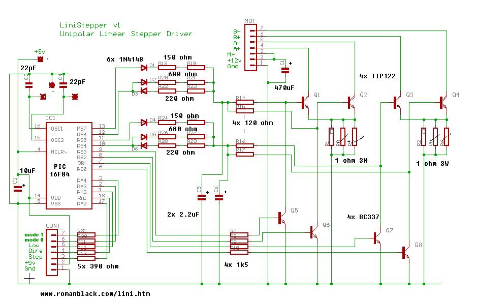
Question:
Can I change bipolar transistor TIP122 to mosfet irf830. If I change it,
maybe I can delete all of bc337 and r7-r10 1.5k resistors. And drive mosfet from
PIC without anything. |
|
|
Ttelmah
Guest
|
|
| Posted: Wed Mar 30, 2005 2:37 am |
|
|
On your question about 1/8th step, the answer is 'no'. Just controlling the voltage like this, will work to some extent, but only at very low step rates. The problem is that if you limit the voltage drive, and then try to step through these phases at any faster rate, you risk skipping a step. The normal way is to adjust the phase current, rather than the voltage, so that as the step rate increases, the voltage is still applied at full level, but for a shorter time. Also motors are generally not linear when microstepped, so either a more expensive motor needs to be used, or the controller has to adjust for the non linearity. On a 1/8th step, it'd probably be reasonable, but for anything finer, this becomes complex.
Now the circuit given, looks slightly dangerous!. The lack of diodes to clamp the flyback, is a fairly sure way of killing transistors. In the example given, the author, is probably just relying on overrating the transistors massively, and limiting the switching speeds. Changing to FETs, would alter the drives enough, that the problem may well re-appear. On FETs, don't rely on the internal diodes, unless you select a FET, that has a proper diode built in (rather than just the diode action of the FET itself).
The circuit is designed to allow some microstepping control, and if you want to use it, run it 'as is'.
Seriously, there are thousands of simple stepper driver circuits on the web, and hundreds of IC's, that do the job, and 're-inventing the wheel', is complex, and likely to give problems. At one end of the market, a small motor, can be driven without current control, by almost any of the simple IC's like the ULN2064, and at low speeds run fine. For real performance, a proper driver IC, like the Allegro SLA7024, gives current controlled drive.
Both of these approaches are easy to use, and give 1/4 stepping (with suitable code), very simply. If you want to microstep, go to the Allegro site, and look at their products. They offer IC's that handle microstepping for you (SLA7060M to 7062M), and will do a far nicer job. Offering 1/16th step control of the PWM.
Best Wishes |
|
|
|
|
You cannot post new topics in this forum
You cannot reply to topics in this forum
You cannot edit your posts in this forum
You cannot delete your posts in this forum
You cannot vote in polls in this forum
|
Powered by phpBB © 2001, 2005 phpBB Group
|

