 |
 |
| View previous topic :: View next topic |
| Author |
Message |
Zek_De
Joined: 13 Aug 2016
Posts: 100


|
| Multiple byte read (Problem) |
 Posted: Tue Dec 13, 2016 3:55 am Posted: Tue Dec 13, 2016 3:55 am |
 |
|
Hi friends,
I'm trying to use this reading style but it didnt work despite all trying. These results are same out[0] = out[1] why???
| Code: |
i2c_start();
i2c_write(0xD2);
i2c_write(OUT_X_L);
i2c_start();
i2c_write(0xD3);
out[0] = i2c_read(1);
out[1] = i2c_read(0);
i2c_stop(); |
and also these codes must work as well right, below:
| Code: |
i2c_start();
i2c_write(0xD2);
i2c_write(OUT_X_L);
i2c_start();
i2c_write(0xD3);
out[0] = i2c_read(1);
out[1] = i2c_read(1);
out[2] = i2c_read(1);
out[3] = i2c_read(1);
out[4] = i2c_read(1);
out[5] = i2c_read(0);
i2c_stop();
|
They belong L3G4200D.
Thanks in advance |
|
 |
Ttelmah
Joined: 11 Mar 2010
Posts: 19328
|
|
| Posted: Tue Dec 13, 2016 4:52 am |
|
|
Are you using a 3.3v PIC?.
The commonest problem with these is people not realising that the output can't drive a standard 5v PIC I2C input.... |
|
|
temtronic
Joined: 01 Jul 2010
Posts: 9162
Location: Greensville,Ontario
|
|
| Posted: Tue Dec 13, 2016 7:35 am |
|
|
With any.. no, EVERY I2C device , it's always a great idea to use PCM P's 'I2C Scanner program before you code your program. It can be fouund in the 'code library'.
It's a fast,easy way to confirm your I2C connections and other hardware is probably OK.
You also don't say what the data is, but I assume it's 255, 0xFF, or all highs ? |
|
|
Ttelmah
Joined: 11 Mar 2010
Posts: 19328
|
|
| Posted: Tue Dec 13, 2016 9:40 am |
|
|
The problem (as so very often), is 'lack of data'.
You do understand that for the device address to be 0xD2/D3, the SA0 pin has to be pulled high?.
For a 3.3v I2C device (and especially one that supports 400KHz signalling), the pull-up resistors will need to be quite low. Typically 1.2KR.
You do understand the point about 3.3v signalling. Chips like the Arduino have I2C inputs that don't actually meet the specifications. They accept signals as 'high' at only about 2.5v. 5v I2C, requires the signal to go up to 4v, which a 3.3v device can't so (on many PIC's, you can program a lower level by selecting the option 'SMBUS') - this is dependant on your PIC.
The above raises the next problem. No details of the PIC, no setup code shown, etc. etc....
Now Temtronic makes a very good point. The basic things are always 'test one part at a time'. So:
1) Flash an LED. Does it work?. Correct speed?.
2) For I2C, then test with PCM_programmers scanner. Is the device being reported where it is meant to be?. |
|
|
Zek_De
Joined: 13 Aug 2016
Posts: 100
|
|
| Posted: Tue Dec 13, 2016 10:18 am |
|
|
Sorry my late reply ,
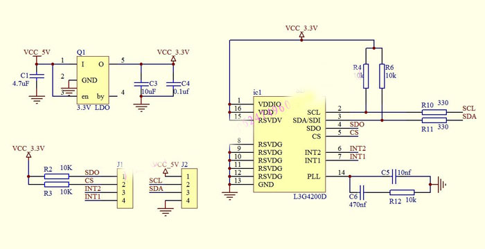
Pic is 18F4550 and I'm sending my full codes.Normally I take true values if I use single byte reading in this case no problem but if I use multiply ,like I say out[0] and out[1] is equals with eachother.
[code]#include <L3G4200D.h>
#include <stdlib.h>
#include <lcd.c>
#include <math.h>
#define WHO_AM_I 0x0F
#define CTRL_REG1 0x20
#define CTRL_REG2 0x21
#define CTRL_REG3 0x22
#define CTRL_REG4 0x23
#define CTRL_REG5 0x24
#define CTRL_REG6 0x25
#define FIFO_CTRL_REG 0x2E
#define FIFO_SRC_REG 0x2F
#define OUT_X_L 0x28
#define OUT_X_H 0x29
#define OUT_Y_L 0x2A
#define OUT_Y_H 0x2B
#define OUT_Z_L 0x2C
#define OUT_Z_H 0x2D
#define STATUS_REG 0x27
#define REFERENCE 0x25
#define INT1_CFG 0x30
#define INT1_SRC 0x31
#define INT1_THS_XH 0x32
#define INT1_THS_XL 0x33
#define INT1_THS_YH 0x34
#define INT1_THS_YL 0x35
#define INT1_THS_ZH 0x36
#define INT1_THS_ZL 0x37
#define INT1_DURATION 0x38
#define OUT_TEMP 0x26
#define x_eksen 0
#define y_eksen 1
#define z_eksen 2
/*enum eksenler {
x_eksen = 0,
y_eksen = 1,
z_eksen = 2,
};*/
signed int8 xMSB=0;
signed int8 xLSB=0;
signed int8 yMSB=0;
signed int8 yLSB=0;
signed int8 zMSB=0;
signed int8 zLSB=0;
signed int16 Rm[3]={0};
float32 Ro[3]={0};
float32 Rth[3]={0};
float32 deltaR[3]={0};
signed int16 temperature = 0;
float32 angle[3]={0};
unsigned int16 timer_0=0;
signed int8 out[6]={0};
signed int16 Rk[3]={0};
void init(); //Fonksiyon prototipleri
void Setup_Gyro();
void Gyroscope_Write(unsigned int8 yazilacakAdres,unsigned int8 deger);
signed int8 Gyroscope_Read(unsigned int8 okunacakAdres);
void Gyroscope_Values_Raw();
void Gyroscope_Values();
void Calibrate_Gyro();
unsigned int8 Get_Temperature();
void Interrupt_To_Temperature_and_Calibrating();
void main() //Ana Fonksiyon
{
init();
Setup_Gyro();
Calibrate_Gyro();
unsigned int8 cikis=0;
while(true)
{
// Gyroscope_Values();
//unsigned int8 hpfReset;
cikis = Gyroscope_Read(STATUS_REG);
while(bit_test(cikis,3)==0)
{
cikis = Gyroscope_Read(STATUS_REG);
}
i2c_start();
i2c_write(0xD2);
i2c_write(OUT_X_L);
i2c_start();
i2c_write(0xD3);
out[0] = i2c_read(1);
out[1] = i2c_read(0);
/*out[2] = i2c_read();
out[3] = i2c_read(1);
out[4] = i2c_read(1);
out[5] = i2c_read(0); */
i2c_stop();
// Rk[0] = make16(out[1],out[0]);
// for (int j = 0; j<3; j++)
// {
deltaR[0] = (float32)Rk[0] - Ro[0];
if (abs(deltaR[0]) > Rth[0])
{
angle[0] = angle[0] + deltaR[0] * 0.07 * 0.021686; //0.021686
}
// }
printf(lcd_putc,"\f");
lcd_gotoxy(1,1);
printf(lcd_putc,"X:%d",out[x_eksen]);
lcd_gotoxy(9,1);
printf(lcd_putc,"Y:%d",out[y_eksen]);
lcd_gotoxy(1,2);
printf(lcd_putc,"Z:%d",out[z_eksen]);
// lcd_gotoxy(9,2);
// printf(lcd_putc,"C:%Ld",temperature);
delay_ms(500);
/* if(timer_0 >= 1526) //20 s
{
printf(lcd_putc,"\f");
lcd_gotoxy(1,1);
printf(lcd_putc,"Stop!");
delay_ms(1000);
Calibrate_Gyro();
temperature = Get_Temperature();
timer_0=0;
angle[x_eksen]=0;
angle[y_eksen]=0;
angle[z_eksen]=0;
printf(lcd_putc,"\f");
lcd_gotoxy(1,1);
printf(lcd_putc,"Done...");
delay_ms(500);
} */
}
}
//#############################################################################
void init() //Denetleyici ayarları
{
setup_psp(PSP_DISABLED);
setup_timer_1(T1_DISABLED);
setup_timer_2(T2_DISABLED,0,1);
setup_timer_3(T3_DISABLED);
setup_adc_ports(NO_ANALOGS);
setup_adc(ADC_OFF);
setup_CCP1(CCP_OFF);
setup_CCP2(CCP_OFF);
setup_comparator(NC_NC_NC_NC);
//Timer0 kuruluyor
setup_timer_0(RTCC_INTERNAL | RTCC_DIV_256 |RTCC_8_BIT);
set_timer0(0);
enable_interrupts(INT_timer0);
enable_interrupts(GLOBAL);
//Timer0 kuruldu.
lcd_init();
delay_ms(20);
lcd_gotoxy(1,1);
printf(lcd_putc,"Don't Move!");
}
//&&&&&&&&&&&&&&&&&&&&&&&&&&&&&&&&&&&&&&&&&&&&&&&&&&&&&&&&&&&&&&&&&&&&&&&&&&&&&&&&&&&&&&&&&&&&&&&&&&&&&&&&&
void Setup_Gyro()
{
Gyroscope_Write(CTRL_REG2,0b00100100);//Normal mode ,High pass filter cut off frecuency:8
Gyroscope_Write(CTRL_REG3,0b00001000);// I2_DRDY,I2_WTM,I2_ORun,I2_Empty etkin ,push-pull--FIFO etkin olmadığı durumda push-pull hariç diğerleri geçersiz
Gyroscope_Write(CTRL_REG4,0b10110000);//BDU:1,2000 dps,self-test disabled(normal mode)
Gyroscope_Write(CTRL_REG5,0b00000000);//HPF disabled - Data in DataReg and FIFO are non-high-passfiltered - Data in DataReg and FIFO are non-highpass- filtered
/*
Gyroscope_Write(REFERENCE,0b00000000);
Gyroscope_Write(INT1_THS_XH,0b00000000);
Gyroscope_Write(INT1_THS_XL,0b00000000);
Gyroscope_Write(INT1_THS_YH,0b00000000);
Gyroscope_Write(INT1_THS_YL,0b00000000);
Gyroscope_Write(INT1_THS_ZH,0b00000000);
Gyroscope_Write(INT1_THS_ZL,0b00000000);
Gyroscope_Write(INT1_DURATION,0b00000000);
Gyroscope_Write(INT1_CFG,0b00000000);*/
Gyroscope_Write(CTRL_REG1,0b11001111); // 800Hz,30 cut-off/ X,Y,Z etkin
delay_ms(252);
}
//&&&&&&&&&&&&&&&&&&&&&&&&&&&&&&&&&&&&&&&&&&&&&&&&&&&&&&&&&&&&&&&&&&&&&&&&&&&&&&&&&&&&&&&&&&&&&&&&&&&&&&&&&
Last edited by Zek_De on Tue Dec 13, 2016 2:39 pm; edited 1 time in total |
|
|
Zek_De
Joined: 13 Aug 2016
Posts: 100
|
|
| Posted: Tue Dec 13, 2016 10:21 am |
|
|
 |
|
|
temtronic
Joined: 01 Jul 2010
Posts: 9162
Location: Greensville,Ontario
|
|
| Posted: Tue Dec 13, 2016 11:37 am |
|
|
It can never work.....That PIC is a 5 volt device, and your peripheral is a 3 volt device.
Please check the 18F4550 datasheet, electrical spec, figure 28-1( I think...going from old memory...)
4550 is only good down to maybe 4.2-4.3 volts.....
I call this Error 53. Cure is to either use the 'L' rated version ( good for 3 volts) or use some form of 'logic level translation' devices ( 5>3, 3>5).
Jay |
|
|
Ttelmah
Joined: 11 Mar 2010
Posts: 19328
|
|
| Posted: Tue Dec 13, 2016 12:19 pm |
|
|
Actually it 'just can'. He is using software I2C, and the 4550 at 5v. It'll be running well below the 400K he requests, and the input threshold on B0, in software mode, is a standard TTL input, so it can just work.
Means though he needs to be sure to be in software mode. Add FORCE_SW to the I2C setup to be sure. It should default to software mode.
However the pullups are much too big. and the series resistors will make things worse. Great for reducing reflections if the bus was working really fast, but with the dubious voltages they will make the margins even lower....
The SDO line on the L3G chip needs to be pulled high (in I2C mode this programs the low bit of the I2C address - having it floating is good way of having unreliable operation). Reduce the series resistors to 50R, and reduce the pullups to 1K2R, and he has a chance of it working. Not ideal, but it can work at a low rate.
It's a poor design, as you say much better to use a 5v chip, or one that supports SMBUS signalling. |
|
|
Zek_De
Joined: 13 Aug 2016
Posts: 100
|
|
| Posted: Tue Dec 13, 2016 12:25 pm |
|
|
| Friends but these codes if I use signed int8 Gyroscope_Read(unsigned int8 okunacakAdres) function ,no problem ,it dosnt work just multiply read ,so is it necessary your offers maybe different problem ,what excatly do I do? |
|
|
Zek_De
Joined: 13 Aug 2016
Posts: 100
|
|
| Posted: Tue Dec 13, 2016 12:32 pm |
|
|
| Also could you recommend 5-3.3 V converter and this is a module |
|
|
Ttelmah
Joined: 11 Mar 2010
Posts: 19328
|
|
| Posted: Tue Dec 13, 2016 1:07 pm |
|
|
The reason it is not incrementing, is in the data sheet......
Your addresses are wrong for this.
The address for auto increment, will be:
| Code: |
#define OUT_X_L 0x28
#define OUT_X_L_INC 0xA8
|
etc.. The top bit of the register address has to be set to enable auto increment.
However 'long term' your reliability is likely to be worse the faster you try to transfer data - improve the interface to avoid this. |
|
|
Zek_De
Joined: 13 Aug 2016
Posts: 100
|
|
| Posted: Tue Dec 13, 2016 1:45 pm |
|
|
| I did it but it doesnt work ? and I m so tired because of I m laboring a few days. My values x:36 or different y:0. And I dont understand why A8 I didnt see in datasheet |
|
|
Zek_De
Joined: 13 Aug 2016
Posts: 100
|
|
| Posted: Tue Dec 13, 2016 1:49 pm |
|
|
Sorry I saw SUB(7) must be equal to 1, while SUB(6-0) represents the
address of the first register to be read. But it doesnt work new codes
i2c_start();
i2c_write(0xD2);
i2c_write(OUT_X_L_INC);
i2c_start();
i2c_write(0xD3);
out[0] = i2c_read(1);
out[1] = i2c_read(0);
/*out[2] = i2c_read();
out[3] = i2c_read(1);
out[4] = i2c_read(1);
out[5] = i2c_read(0); */
i2c_stop();
Still am I wrong |
|
|
Ttelmah
Joined: 11 Mar 2010
Posts: 19328
|
|
| Posted: Tue Dec 13, 2016 1:51 pm |
|
|
For a level translator, look at the TCA9406, or the PCA9306. There are several others, but these are readily available.
It should work with the top bit of each register address set.
From the data sheet:
| Code: |
The 7 LSb
represent the actual register address while the MSB enables address auto-increment. If the
MSb of the SUB field is 1, the SUB (register address) is automatically incremented to allow
multiple data read/write.
|
I really would try with smaller pull-ups. It may simply be that the data is not quite being sent as you expect. |
|
|
Zek_De
Joined: 13 Aug 2016
Posts: 100
|
|
| Posted: Tue Dec 13, 2016 1:56 pm |
|
|
Master ST SAD+W SUB SR SAD+R MAK MAK NMAK SP
Slave SAK SAK SAD DATA DATA DATA
and also why are there 3 Data . it necessary to read 2 Data ,X MSB and X LSB .Is this just example notation?
Last edited by Zek_De on Tue Dec 13, 2016 2:19 pm; edited 1 time in total |
|
|
|
|
You cannot post new topics in this forum
You cannot reply to topics in this forum
You cannot edit your posts in this forum
You cannot delete your posts in this forum
You cannot vote in polls in this forum
|
Powered by phpBB © 2001, 2005 phpBB Group
|

