 |
 |
| View previous topic :: View next topic |
| Author |
Message |
lozi_dani
Joined: 22 Jan 2016
Posts: 40


|
| Interfacing DC Motors with PIC18F4550 (SOLVED) |
 Posted: Sat Jan 30, 2016 8:34 am Posted: Sat Jan 30, 2016 8:34 am |
 |
|
Hi everyone!
Now I'm trying to run a DC motor with the PIC 18F4550. I think that I'm going for the right way because sometimes the motor runs, but sometimes doesn't.. And this is the main reason why I need to open this thread.
I'm going to post the code I'm using and a picture with the schematic. This schematic is shown with Proteus, but I'm not using Proteus to do this project, it is only used to show you how I'm connecting everything in the board.
CCS code:
| Code: |
#include <18F4550.h>
#FUSES HS,NOWDT,NOPROTECT,PUT,NOBROWNOUT,NOLVP,NOPBADEN
//add NOPBADEN or port B will wake up for ADC operation
#use delay(clock=20000000)
#byte TRISA=0x86
#byte TRISC=0x87
#define MOTOR PIN_A1
///// Funcion Init_Motor /////
///// Pin config for the DC motor /////
void Init_Motor(void)
{
bit_clear(TRISA,1); //RA1 as output. Go forward when RA1=1 && PIN_C1=1 and move backwards when RA1=0 && PIN_C1=1
output_low(PIN_C1); //Disable motor output
return;
}
///// Fin Init_Motor() /////
///// Funcion Adelante /////
///// motor forwards /////
void Adelante(void)
{
output_high(PIN_C1); //Habilito salida motor
output_high(MOTOR); //Motor avanza
return;
}
///// Fin Adelante() /////
///// Funcion Atras /////
///// motor backwards/////
void Atras(void)
{
output_high(PIN_C1); //Habilito salida motor
output_low(MOTOR); //Motor retrocede
return;
}
///// Fin Atras() /////
///// Funcion Parado /////
///// motor stop /////
void Parado(void)
{
output_low(PIN_C1); //Deshabilito salida motor
return;
}
///// Fin Parado() /////
///// Funcion Main /////
///// Funcion principal para el movimiento /////
void main()
{
set_tris_d(0x00);
output_high(PIN_D1); //debugger led
delay_ms(1000);
Init_Motor();
output_low(PIN_D1); //debugger led
delay_ms(1000);
while(true){
output_high(PIN_D1); //debugger led
delay_ms(1000);
Adelante();
output_low(PIN_D1); //debugger led
delay_ms(3000);
Parado();
output_high(PIN_D1); //debugger led
delay_ms(1000);
Atras();
output_low(PIN_D1); //debugger led
delay_ms(1000);
Parado();
output_high(PIN_D1); //debugger led
delay_ms(1000);
output_low(PIN_D1); //debugger led
delay_ms(1000);
}
}
|
Now I explain the code:
The only thing that this code does is go forward X seconds, stop X seconds, go backward X seconds, stop X seconds in a infinite while loop. The LED is only used to debug the program and to know where the program could stop.
The problem:
What I can see is that the program goes until the end and does the while perfectly, but the motor in some iterations runs and in others doesn't, which is strange I think. And I don't know if it could be a problem from the code or from the connections in my board.
I don't know if I can do this but if it could be useful, I could upload a video of how works physically.
Image of the connections I'm using:
****Sorry but i'm trying to post my image but I can't haha! How can I do this?????***
Last edited by lozi_dani on Thu Mar 17, 2016 10:08 am; edited 1 time in total |
|
 |
gpsmikey
Joined: 16 Nov 2010
Posts: 588
Location: Kirkland, WA
|
|
| Posted: Sat Jan 30, 2016 10:22 am |
|
|
1) to post an image, you need to upload it to a public hosting site - there are a number of free ones (I use photobucket) then post the link to that image here.
2) Not sure on your code, but the most likely suspect for "it works sometimes" or "works strangely" is in the wiring and transient suppression - dc motors (well anything with a coil in it) is notorious for startup currents, transients and all sorts of other strange things. You need to pay careful attention to how you are controlling the motor and how the motor is grounded otherwise you get things like spikes that will reset the micro, drops in the supply that will reset the micro etc.
mikey
_________________
mikey
-- you can't have too many gadgets or too much disk space !
old engineering saying: 1+1 = 3 for sufficiently large values of 1 or small values of 3 |
|
|
Ttelmah
Joined: 11 Mar 2010
Posts: 19338
|
|
| Posted: Sat Jan 30, 2016 11:43 am |
|
|
Gpsmikey has mentioned several of the problems. However the biggest is normally the overshoot when the motor is switched _off_ (the combination of the flywheel from the inductor, and the generation from the motor). The energy from both of these has to go _somewhere_, and if there isn't circuitry to handle this, it will induce very large voltages, which will go through the PIC...
Get the circuit posted, and we can see if you are handling this. |
|
|
lozi_dani
Joined: 22 Jan 2016
Posts: 40
|
|
|
newguy
Joined: 24 Jun 2004
Posts: 1903
|
|
| Posted: Sun Jan 31, 2016 10:18 pm |
|
|
| Is that it? No capacitors? |
|
|
lozi_dani
Joined: 22 Jan 2016
Posts: 40
|
|
| Posted: Mon Feb 01, 2016 2:30 am |
|
|
In the examples that I saw there are no capacitors. Furthermore, the motor runs when I run the code, but only sometimes.
Do you think that the poblem could be that I have no capacitors? Or to have or not capacitors must not give that problem?? |
|
|
Ttelmah
Joined: 11 Mar 2010
Posts: 19338
|
|
| Posted: Mon Feb 01, 2016 2:37 am |
|
|
Start with the phrase: Data is your friend.
For any chip the very first thing you _must_ do is look at the data sheet.
Look at the 'example' circuits on the data sheet for the L293. Look at the two Vcc connections, and then read what it says for each:
Vcc1 5-V supply for internal logic translation.
Vcc2 Power VCC for drivers 4.5 V to 36 V.
Not the same supply.
For a 12v motor, Vcc2, needs to be connecting to 12v, and Vcc1 to the PIC Vdd. Even if you are running the motor off 5v, the motor connection, and the processor connection should be separate.
Then understand that even if you have a 10A supply, this _will_ take time to respond to changes. When you switch the driver 'on', the current will rise rapidly to several times the motor rating for a few nSec. This is why the driver that is rated for 600mA, has a 'momentary' peak rating of 1.2A, to allow it to handle this. This current has to come from somewhere in the few moments it takes the supply to respond (and since the connections _will_ have some inductance, the supply will not actually 'see' the change for a moment after it happens). This is the first reason why there should be a 'reservoir' capacitor close to the chip on the Vcc2 rail.
Then the 'D' chip has overshoot diodes built in, to trap the voltages already referred to when the motor is switched 'off'. These trap the voltages 'into' the Vcc2 rail. If you look at Figure 5 in the data sheet (assuming you have the Texas sheet), you will see that if the 'output' pin tries to go above Vcc2, the diode will stop it from going more than about 0.6v above Vcc2, and the energy here will then be fed back into the Vcc2 connection. There therefore most be something to connected to Vcc2 to prevent the pin from being taken significantly above it rated voltage. This again the reservoir capacitor can handle.
Then the same is true of the PIC itself. Though it may only draw a few mA 'average', at the moment some of the gates internally switch, there can be instantaneous currents, literally for pSec, that need to be supplied close to the chip. hence the standard recommendation is that there should be a small capacitor like 100nF ceramic, immediately adjacent to every supply pin on the chip. Microchip do drawings on some of their data sheets, of 'recommended connections', and these will show the capacitors.
So as Newguy says 'No capacitors'.....
Generally you need to ensure that the 'power' connections (GND, and Vcc2 to the L293), run back to the supply using routes that do not go 'past' any of the 'logic' connections. Single wires straight back to the supply, with the Vcc2 capacitor(s) on them.
Again generally, though it is tempting to think 'bigger is better' on things like reservoir capacitors, there is a 'caveat', that standard electrolytic capacitors, though they give large capacitances in small sizes, do this at a 'cost' of not offering really good high frequency performance. This is why smaller capacitors (like the 100nF mentioned) are needed close to anything that generates high frequency changes in demand. This is also why you will commonly see in 'example' circuits 'pairs' of capacitors used (100uF in parallel with 0.1uF for example), with the small capacitor serving to help the larger one handle 'fast' changes. |
|
|
lozi_dani
Joined: 22 Jan 2016
Posts: 40
|
|
| Posted: Mon Feb 01, 2016 10:49 am |
|
|
Amazing explanation! Thanks to both!
Let me ask you something, you said that it is necessary a capacitor with Vcc2, and also that Vcc2 needs 12v, which is that the data sheet of the driver says.
But what happens if I only have a power supply of 5v? I'm using a little battery which gives me the maximum of 5v.
Maybe some of you could show me an example of how to do the connections of Vcc2 with my power supply if it is possible and with the capacitors?
Ttelmah you say that Vcc1 must be connected to the PIC Vdd, what does means? You mean that must be connected to the same supply or with the Vdd PIN of the PIC directly?
Anyway, about the code, do you think that, with the correct physical connections, could works without problems? Or you think that something there can do that the main purpose of the code doesn't works?
Last edited by lozi_dani on Mon Feb 01, 2016 11:02 am; edited 1 time in total |
|
|
Ttelmah
Joined: 11 Mar 2010
Posts: 19338
|
|
| Posted: Mon Feb 01, 2016 10:59 am |
|
|
I only say 12v, because your circuit shows the motor as 12v....
If you have a battery, and a lower voltage motor, then this can be fed off the battery supply, but don't connect the pins together at the chip. Have a separate wire with a reasonably large capacitor, feeding straight back to the battery. |
|
|
lozi_dani
Joined: 22 Jan 2016
Posts: 40
|
|
| Posted: Mon Feb 01, 2016 11:21 am |
|
|
Noooo sorry. It is an error, motor doesn't goes at 12v, proteus put that and I didn't saw it to remove it. The motor doesn't go to 12v, it is a simple motor. I took it from a rc car I had, and this car works with a normal battery supply of 5v.
So how do you think the connections must be? According with the tips you gave me before?
I have studied computer engineering and sometimes i don't undersand some things about electronic =( |
|
|
Ttelmah
Joined: 11 Mar 2010
Posts: 19338
|
|
| Posted: Mon Feb 01, 2016 1:04 pm |
|
|
Motor from an RC car?.
Have you tested what current it draws?
The ones I used when doing RC cars, were 50A at startup. You may well be overloading the driver... |
|
|
lozi_dani
Joined: 22 Jan 2016
Posts: 40
|
|
| Posted: Thu Mar 17, 2016 1:46 am |
|
|
Hi everyone!
Sorry for answer now and don't say nothing in this time.
I've already fixed the problem. When I arrive at home I will post the whole code, connections and components that I used to explain how i made it works. I think it could be useful for someone.
The main problem was so stupid, but is one of that thing you don't put care when you are going fast doing everything.
The problem was the MCLR pin of my PIC. I'm programming my PIC using the PICKIT 3, and this requires to have the MCLR pin of the PIC connected to the PICKIT 3. After programming it, I didn't put the MRCL pin to Vdd, which generates inconsistencies because the PIC doesn't know what is receiving in that pin.
I've tested my motors to see how must current and voltage need to work, and need around 3-5 volts, with an amperage between 0,2A - 0,5A, so I discarded that the problem where in the motors.
After I post everything I will start to learn how works the stepper motors with PWM. I never tried it and I'm curious in how it works. Have someone any advice before I start doing it?
Thanks to everyone for your help!
PD: I have another post about interfacing the SR-HC04 ultrasonic sensor with this PIC, I will post the schematic of the connections too when I arrive at home and I will post here the link if anyone like to see =) |
|
|
lozi_dani
Joined: 22 Jan 2016
Posts: 40
|
|
| Posted: Thu Mar 17, 2016 10:07 am |
|
|
Hi again!
Some things before the code:
This project consists in programmig a DC motor with PIC18F4550. The information you will see here is the code, the connections and the components I've used. If someone has some doubt about this, write in this post and I will answer if I know how haha!
This code shows how a DC motor goes forward and backward each second, turning on and off a green debugger led to see where is the code going along the execution:
| Code: |
#include <18F4550.h>
#FUSES HS,NOWDT,NOPROTECT,PUT,NOBROWNOUT,NOLVP,NOPBADEN
//add NOPBADEN or port B will wake up for ADC operation
#use delay(clock=20000000)
#byte TRISA=0x86
#byte TRISC=0x87
#define MOTOR1_A PIN_A1
#define MOTOR1_B PIN_A2
//#define MOTOR_DER PIN_A2
///// Funcion Init_Motor /////
///// Configuración de pines para los motores /////
void Init_Motor(void)
{
bit_clear(TRISA,1); //RA1 as output.
bit_clear(TRISA,2); //RA2 as output.
output_low(PIN_C1); //Disable EN1 pin of the driver
return;
}
///// Fin Init_Motor() /////
///// Forward function /////
///// Avanza el motor /////
void Adelante(void)
{
output_high(PIN_C1); //Enable EN1 pin of the driver
output_high(MOTOR1_A);
output_low(MOTOR1_B); //Motor1_A high and Motor1_B low to go forward (see the datasheet specs.)
return;
}
///// Fin Adelante() /////
///// Backward function/////
///// Retrocede el motor /////
void Atras(void)
{
output_high(PIN_C1); //Enable EN1 pin of the driver
output_low(MOTOR1_A);
output_high(MOTOR1_B); //Motor1_A low and Motor1_B high to go backward (see the datasheet specs)
return;
}
///// Fin Atras() /////
///// Stopped function /////
///// Para el motor /////
void Parado(void)
{
output_low(PIN_C1); //Disable EN1 pin of the driver
return;
}
///// Fin Parado() /////
///// Main function /////
///// Funcion principal para el movimiento /////
void main()
{
set_tris_d(0x00);
output_high(PIN_D1); //debugger led
delay_ms(1000);
Init_Motor();
output_low(PIN_D1); //debugger led
delay_ms(1000);
while(true){
output_high(PIN_D1); //debugger led
Adelante(); //Forward
delay_ms(1000);
output_low(PIN_D1); //debugger led
Parado(); //Stop
delay_ms(1000);
output_high(PIN_D1); //debugger led
Atras(); //Backward
delay_ms(1000);
output_low(PIN_D1); //debugger led
Parado(); //Stop
delay_ms(1000);
}
}
|
Note: You can change the time of the delays acording with what you want to achieve.
How it is connected:
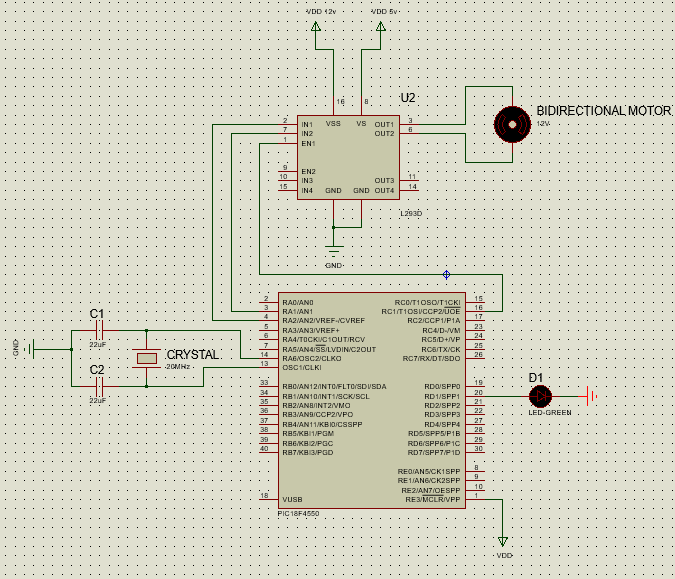
What materials you need:
- PIC18F4550
- Crystal 20MHz
- Driver L293D
- Green Led (1k resistor for the for the LED if needed)
- Capacitors (2 units) 22uF
Advice: Using my own experience, DON'T FORGET to put the MCLR pin of the PIC to Vdd after programming if you are using the PICKIT3 programmer.
I hope this tutorial could be useful for someone! If it is, I will be very greatful if you comment and say that this was good for you. With this, other people could see that this tutorial works.
Thanks to all for all your help during this project!! |
|
|
|
|
You cannot post new topics in this forum
You cannot reply to topics in this forum
You cannot edit your posts in this forum
You cannot delete your posts in this forum
You cannot vote in polls in this forum
|
Powered by phpBB © 2001, 2005 phpBB Group
|

