| View previous topic :: View next topic |
| Author |
Message |
mahdi70
Joined: 05 Jan 2016
Posts: 44


|
| 3 channel pwm with 120 degree phase shift |
 Posted: Sun Jan 24, 2016 4:16 am Posted: Sun Jan 24, 2016 4:16 am |
 |
|
hi buddies
how to generate 3 pwm with 120 degree phase shift to drive gimbal brushless motor..?
like this

tnx alot |
|
 |
Ttelmah
Joined: 11 Mar 2010
Posts: 19504
|
|
| Posted: Sun Jan 24, 2016 4:35 am |
|
|
You can do it using the CCP, with just about any PIC (look at AN857). I have posted this ported to CCS here a while ago, and if you can't find this still have it.
'Better', use a chip that has the PCPWM module, that is designed to do this (PIC18Fxx31). This is covered in AN899. Downside is limited range of chips, and all the models with this have a significant number of errata.
The PWM's available on the DSPIC's can also do this, since they allow multiple timers to be used (AN901).
If your motor is a simple synchronous motor (so no need for sensored/sensorless feedback), this is relatively easier.
Remember you are going to need external drivers for the FETs, and preferably hardware current limiting. The MCP8024, is a very tidy way of handling this. |
|
|
mahdi70
Joined: 05 Jan 2016
Posts: 44
|
|
| Posted: Sun Jan 24, 2016 4:50 am |
|
|
| Ttelmah wrote: | You can do it using the CCP, with just about any PIC (look at AN857). I have posted this ported to CCS here a while ago, and if you can't find this still have it.
'Better', use a chip that has the PCPWM module, that is designed to do this (PIC18Fxx31). This is covered in AN899. Downside is limited range of chips, and all the models with this have a significant number of errata.
The PWM's available on the DSPIC's can also do this, since they allow multiple timers to be used (AN901).
If your motor is a simple synchronous motor (so no need for sensored/sensorless feedback), this is relatively easier.
Remember you are going to need external drivers for the FETs, and preferably hardware current limiting. The MCP8024, is a very tidy way of handling this. |
tnx for reply...i want to build camera stabilizer ...the 18f clock speed is very low for proccess imu data..for this reason i have to use dspic series with 80 mhz clock speed |
|
|
temtronic
Joined: 01 Jul 2010
Posts: 9225
Location: Greensville,Ontario
|
|
| Posted: Sun Jan 24, 2016 6:44 am |
|
|
you should post the make/mdl/specs of the motor+ platform and IMU unit you intend to use,as well as the camera and the 'specs of use' like rate of travel, range of travel,etc.
if you think about it for $100 you can buy a complete quadcopter with camera that is almost rock solid stable and they do NOT use ultra fast micro in them.
Jay
edit: A simple,easy ,discrete 3 phase with 50% duty cycle can be done using a Johnson counter. The 'trick' is to fed it's clock at 6X the desired frequency of the output. This linl..http://www.allaboutcircuits.com/textbook/digital/chpt-12/ring-counters/ ... scroll down to near the bottom of the page... it's just one example. This might work for you. It does allow a less expensive PIC to be used. |
|
|
mahdi70
Joined: 05 Jan 2016
Posts: 44
|
|
| Posted: Sun Jan 24, 2016 7:17 am |
|
|
| temtronic wrote: |
if you think about it for $100 you can buy a complete quadcopter with camera that is almost rock solid stable and they do NOT use ultra fast micro in them.
|
ultra fast micro can help to have high accurate...
this is my quadrotor that i build it .>>>>>http://s7.picofile.com/file/8235084068/Untitled.png |
|
|
temtronic
Joined: 01 Jul 2010
Posts: 9225
Location: Greensville,Ontario
|
|
| Posted: Sun Jan 24, 2016 8:03 am |
|
|
a slower PIC using integer math is a LOT faster than a faster PIC using FP math !
CPU clock speed is NOT the ONLY way to get great performance. I've got an old Z80 based system with a 2MHz clock that outperforms a PC for some tasks. And a 6800 at 8MHz that does things a P5/Win7 can't do.
Jay |
|
|
Ttelmah
Joined: 11 Mar 2010
Posts: 19504
|
|
| Posted: Sun Jan 24, 2016 9:51 am |
|
|
For a camera, most people going DIY on this use a standard BLDC motor, driven like the slave of a Selsyn motor.
As such, very low speeds indeed, no acceleration profile needed etc..
What always puzzles me is why they don't use stepper motors for this. Some commercial systems do. A 400 step per rev motor, microstepped *16, gives you potentially 6400 positions per rev. Going beyond this, the accuracy of microstepping tends to degrade, except with motors specially designed for this, but the same is true of BLDC motors. I did an optical alignment system some years ago, using a really high quality micro stepped motor operated like this, and could position a light beam accurately on a sensor as the vehicle went across rough terrain at speed. Nice thing is that micro stepping controllers are an 'off the shelf' item, and then the PIC only has to send step/direction pulses as needed. Makes the code a lot simpler. |
|
|
mahdi70
Joined: 05 Jan 2016
Posts: 44
|
|
| Posted: Sun Jan 24, 2016 10:48 am |
|
|
| temtronic wrote: | a slower PIC using integer math is a LOT faster than a faster PIC using FP math !
CPU clock speed is NOT the ONLY way to get great performance. I've got an old Z80 based system with a 2MHz clock that outperforms a PC for some tasks. And a 6800 at 8MHz that does things a P5/Win7 can't do.
Jay |
tnx for your help...i used the float var in my source code...because my source is heavily.. |
|
|
mahdi70
Joined: 05 Jan 2016
Posts: 44
|
|
| Posted: Sun Jan 24, 2016 10:55 am |
|
|
| Ttelmah wrote: | For a camera, most people going DIY on this use a standard BLDC motor, driven like the slave of a Selsyn motor.
As such, very low speeds indeed, no acceleration profile needed etc..
What always puzzles me is why they don't use stepper motors for this. Some commercial systems do. A 400 step per rev motor, microstepped *16, gives you potentially 6400 positions per rev. Going beyond this, the accuracy of microstepping tends to degrade, except with motors specially designed for this, but the same is true of BLDC motors. I did an optical alignment system some years ago, using a really high quality micro stepped motor operated like this, and could position a light beam accurately on a sensor as the vehicle went across rough terrain at speed. Nice thing is that micro stepping controllers are an 'off the shelf' item, and then the PIC only has to send step/direction pulses as needed. Makes the code a lot simpler. |
yes ...but i think the stepper motor Weight is high...what your opinion? |
|
|
Ttelmah
Joined: 11 Mar 2010
Posts: 19504
|
|
| Posted: Sun Jan 24, 2016 11:11 am |
|
|
Same for a given torque as the BLDC.....
Look at large diameter ultraflat designs like:
<http://en.nanotec.com/products/169-sp10-sp55-permanent-magnet-stepper-motors/> |
|
|
mahdi70
Joined: 05 Jan 2016
Posts: 44
|
|
| Posted: Mon Jan 25, 2016 3:25 pm |
|
|
| Ttelmah wrote: | Same for a given torque as the BLDC.....
Look at large diameter ultraflat designs like:
<http://en.nanotec.com/products/169-sp10-sp55-permanent-magnet-stepper-motors/> |
tnx |
|
|
mahdi70
Joined: 05 Jan 2016
Posts: 44
|
|
| Posted: Mon Jan 25, 2016 3:31 pm |
|
|
but i dont know yet how to shift the phase...I'm confused....I have already bought gimbal motor and cant use step motor..i search about johnson counter but dont Understand Anything
Someone can help me?
tnx |
|
|
temtronic
Joined: 01 Jul 2010
Posts: 9225
Location: Greensville,Ontario
|
|
| Posted: Mon Jan 25, 2016 4:05 pm |
|
|
Please post make/model/details about the gimbal motor you have, a link to the datasheeet would be very helpful !
Jay |
|
|
mahdi70
Joined: 05 Jan 2016
Posts: 44
|
|
| Posted: Mon Jan 25, 2016 5:01 pm |
|
|
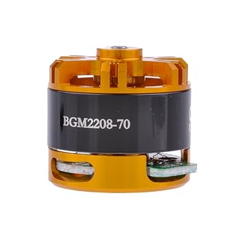
BGM2208--70
Item no.: BGM2208-70
12N14P
Wire: 0.15mm
Turn: 70 T
Motor size: Ф28*26
Shaft: Ф3.17
Ω Ri :13.30ohm
Weight: 40g
 |
|
|
Ttelmah
Joined: 11 Mar 2010
Posts: 19504
|
|
| Posted: Tue Jan 26, 2016 2:26 am |
|
|
The first thing is that you don't want three phase the way you show it.....
BLDC motors like this have forward and reverse drive on each coil. The sequence is:
| Code: |
Phase coil A coil B coil C
1 + - 0
2 0 - +
3 - 0 +
4 - + 0
5 0 + -
6 + 0 -
|
If fact for smooth motion, the '+' energisation (for example), wants to be a synthesised sinusoidal waveform, so a much higher frequency PWM, varying from almost nothing to full power and then back down to almost nothing over the cycle. When the motor is stationary, the current PWM ratio on the correct pins has to continue. Two coils active at any one time.
You need six FET drivers, three energising the coils in a positive direction, and three in a -ve direction. A total of six control pins on the PIC.
For the slow speeds that the gimbal will actually rotate, you may well be able to run without BEMF sensing, and instead treat all motions as if they are initial 'start' operations. AN857, does show how to generate these waveforms from just about any PIC. |
|
|
|


