 |
 |
| View previous topic :: View next topic |
| Author |
Message |
ZD
Joined: 24 Sep 2013
Posts: 16


|
| Error handling problem (#INT_CANERR and #INT_CANIRX ISR) |
 Posted: Sun May 24, 2015 8:04 am Posted: Sun May 24, 2015 8:04 am |
 |
|
Hi,
I have got a 5 nodes which are communicating through CanBus at 62.5kbps. I don't write any code for error handling and after around 8-10 hours (sometimes after 24 hours) one or more nodes doesn't receive messages but they still send messages. Nodes are working on the table and distance between nodes are very short (around 10cm).
I don't understand exactly what should i do when #INT_CANERR or #INT_CANIRX interrupt occurs. I've read the following post. PCM programmer recommended two pdf file to read.
https://www.ccsinfo.com/forum/viewtopic.php?p=32521
For #INT_CANERR (AN215, Figure 6, Error handler FlowChart):
It sends some datas with message ID 0x3FF (System error). But what the other nodes do when they receive an system error message? Is that message ID is fixed or is this decided by the programmer? Or is it using only for determining the fault type by the programmer in firmware developing phase.
For For #INT_CANIRX (Microchip PIC18 Reference Manual, clause 22.9.6.3 and 22.9.7.3.1).
It says that:
"If any type of error occurs during reception of a message, an error will be indicated by the IXRIF bit. This bit can be used (optionally with an interrupt) for autobaud detection with the device in listen-only mode. This error is not an indicator that any action needs to occur, but an indicator that an error has occurred on the CAN bus."
I understand that, there is nothing to do after detecting "invalid message received error". So, what should i do in the ISR?
I don't understand that what should i do after detecting the error type for prevent the repetition of the error.
Which errors are triggering the #INT_CANIRX and which errors are triggering #INT_CANERR interrupt. There is no information from CCS about these error interrupts (or i didn't find it).
In PICmicro 18C MCU Family Reference Manual file, page 485, clause 22.3.1 (DS39500A.pdf), it says;
"However, the 16 messages with the lowest priority (2032-2047) are reserved." It is valid for Standard CAN. Are there any restriction for Extended CAN?
Thanks in advance.
ZD |
|
 |
newguy
Joined: 24 Jun 2004
Posts: 1907


|
|
 Posted: Sun May 24, 2015 10:05 am Posted: Sun May 24, 2015 10:05 am |
 |
|
If possible (if any of your nodes have an LCD or you can get them output serial data that you'd be able to monitor with your computer), get your nodes to read both the transmit and receive error numbers. These two things are readily available by reading the appropriate registers.
What it sounds like is that you have a fundamental issue with your hardware that is manifesting in creeping (monotonically increasing) errors, which is resulting in some nodes going off-bus because of the unhandled errors.
Is your bus linear? Is your bus properly terminated? :
| Code: | | 120R - node - node - node - node - node - 120R |
Are you sure all nodes are transmitting at exactly the same bit rate?
I've been designing and supporting CAN networks for close to 15 years now and the only time that errors have become an issue is when a cable got broken or electrical noise got to a ridiculously high level. CAN is very, very robust. |
|
 |
ZD
Joined: 24 Sep 2013
Posts: 16


|
|
 Posted: Tue May 26, 2015 10:03 am Posted: Tue May 26, 2015 10:03 am |
 |
|
Hi,
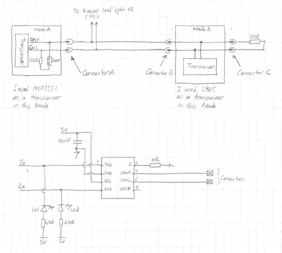
Thank you for your reply. I'm attaching my circuit diagram.

As you can see on the diagram, there are two LED on the RX and TX lines. Are they affect to the performance?
I remove the LED's. After that i get the following measurements.
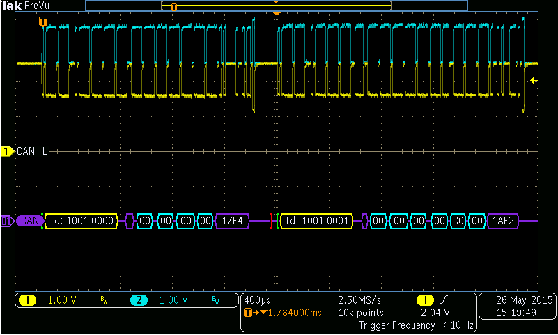
I captured the CANH and CANL lines respect to GND. And they seem ok.

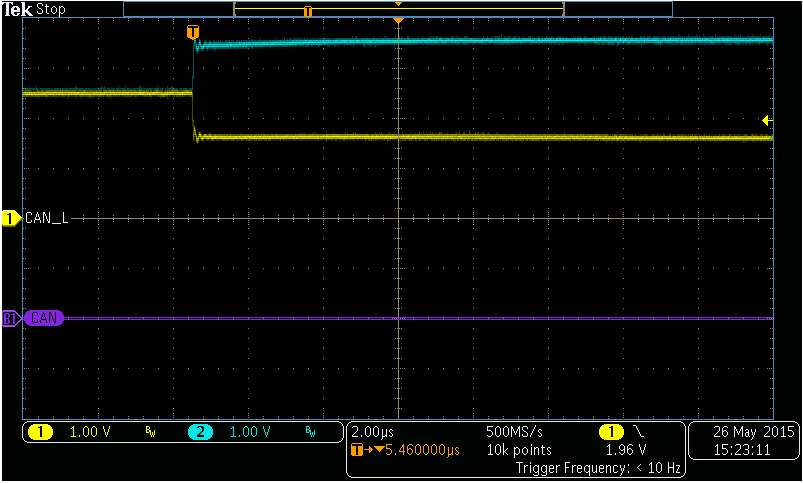
Also, the rise/fall time of CANH and CANL looks fine.

NodeA sends messages every 100ms. My problem is in NodeB. (There were four identical Nodes like NodeB but i removed them. There is only NodeA and NodeB now.)
I wrote a test program to uC. (As i told you, NodeB can still send messages via CanBus when it stops receving.) NodeB sends RXERRCNT and TXERRCNT bytes. Both bytes are always zero. If i unplug and replug the ConnectorA then it sends RXERRCNT to 1. That's it.
I continue to test without LEDs. I'll write here according to news. But, i'm very glad if someone give me some hits about my following questions.
| Quote: |
(1) I don't understand exactly what should i do when #INT_CANERR or #INT_CANIRX interrupt occurs.
For #INT_CANERR (AN215, Figure 6, Error handler FlowChart):
It sends some datas with message ID 0x3FF (System error). (2)But what the other nodes do when they receive an system error message? Is that message ID is fixed or is this decided by the programmer? Or is it using only for determining the fault type by the programmer in firmware developing phase.
For #INT_CANIRX (Microchip PIC18 Reference Manual, clause 22.9.6.3 and 22.9.7.3.1).
It says that:
"If any type of error occurs during reception of a message, an error will be indicated by the IXRIF bit. This bit can be used (optionally with an interrupt) for autobaud detection with the device in listen-only mode. This error is not an indicator that any action needs to occur, but an indicator that an error has occurred on the CAN bus."
(3) I understand that, there is nothing to do after detecting "invalid message received error". So, what should i do in the ISR?
(4) I don't understand that what should i do after detecting the error type for prevent the repetition of the error. Which errors are triggering the #INT_CANIRX and which errors are triggering #INT_CANERR interrupt. There is no information from CCS about these error interrupts (or i didn't find it).
In PICmicro 18C MCU Family Reference Manual file, page 485, clause 22.3.1 (DS39500A.pdf), it says;
"However, the 16 messages with the lowest priority (2032-2047) are reserved." It is valid for Standard CAN. (5) Are there any restriction for Extended CAN?
|
newguy,
Can you give me some example of noisy application enviroments and parameters which CanBus works without problems. For example, Does CanBus work with motor driver (without EMC filter) and with unshilded cable? Can you share your experiences?
Thanks in advance.
Best regards,
ZD |
|
 |
ZD
Joined: 24 Sep 2013
Posts: 16


|
|
 Posted: Tue May 26, 2015 10:55 am Posted: Tue May 26, 2015 10:55 am |
 |
|
Hi again,
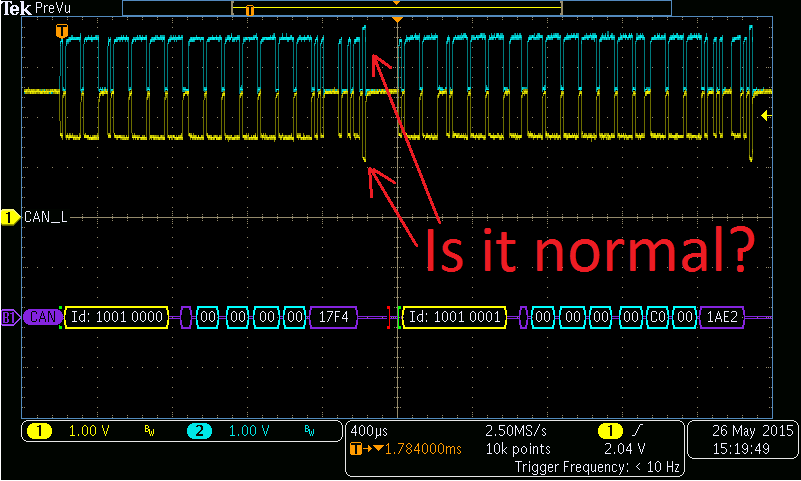
I changed the MDO3000 trigger source to CanBus and it triggers on Error Frame. And in single mode, it doesn't catch any signal. 
To be honest, I'm not sure that is my problem caused from LED? Does anyone have comments?
Is that signal normal?

Regards,
ZD |
|
 |
newguy
Joined: 24 Jun 2004
Posts: 1907


|
|
 Posted: Tue May 26, 2015 12:09 pm Posted: Tue May 26, 2015 12:09 pm |
 |
|
The signals you've posted are clean and normal. I don't like the LEDs you've put on the TX and RX data lines - add the other nodes and see if the errors come back with the LEDs absent.
My recent experience with CAN is in a welding environment. We bundle a 65' 4 conductor (2 power, 2 CAN) cable with 8 welding leads (4 hot, 4 ground) with the CAN network running at 250 kbps. We don't have issues except when the cable develops broken wires or has water ingress or gets run over by a caterpillar. ...And our cable shield is floating at both ends too (don't ask why). Our welding leads carry anywhere from 130A to 250A+ depending on the pass. The welding waveforms are computerized (not straight DC - there is a lot of high frequency noise), and generate a lot of interference. The primary noise coupling mechanism on that lead isn't E field (voltage), it's actually H field (magnetic) because the current in the welding leads is ridiculously high but the welding voltage is usually only about 20V.
I think your problem is not actually with errors, it sounds more like a problem with your CAN reception code on node B.
Have a look at http://ww1.microchip.com/downloads/en/DeviceDoc/70185C.pdf, section 21.10.
If a node goes into "Bus Off" mode because of errors, it completely removes itself from the CAN bus. You say that your node B devices continue to transmit but seem to stop receiving. That makes me think that one of two things is happening: a) either your node A device stops transmitting, or b) your node B code has a flaw with how incoming messages are read/handled.
Speaking from experience and how robust CAN networks are when faced with very high amounts of noise, your problem isn't with the CAN hardware. Your problem is in your code. |
|
 |
|
|
You cannot post new topics in this forum
You cannot reply to topics in this forum
You cannot edit your posts in this forum
You cannot delete your posts in this forum
You cannot vote in polls in this forum
|
Powered by phpBB © 2001, 2005 phpBB Group
|


