 |
 |
| View previous topic :: View next topic |
| Author |
Message |
kenvinh
Joined: 13 Jun 2012
Posts: 12


|
| Hardware SPI make PIC stop |
 Posted: Sat Jun 16, 2012 5:04 am Posted: Sat Jun 16, 2012 5:04 am |
 |
|
I'm trying to test my SPI hardware connection, so I use these code I've found on internet just recently.
I'm using one 18f4550 (20MHz ; CPUDIV4) and one 16f876a (20MHz). Compiler v4.114
About hardware: I connect PIN_D0 on master to PIN_A5 on slave pic
On Master (18F4550 acquiring adc from potentionmeter)
| Code: |
#include <18F4550.h>
#device adc=8
#FUSES NOWDT //No Watch Dog Timer
#FUSES WDT128 //Watch Dog Timer uses 1:128 Postscale
#FUSES PLL5 //Divide By 5(20MHz oscillator input)
#FUSES CPUDIV4 //System Clock by 4
#FUSES USBDIV //USB clock source comes from PLL divide by 2
#FUSES HSPLL //High Speed Crystal/Resonator with PLL enabled
#FUSES FCMEN //Fail-safe clock monitor enabled
#FUSES IESO //Internal External Switch Over mode enabled
#FUSES NOPUT //No Power Up Timer
#FUSES NOBROWNOUT //No brownout reset
#FUSES BORV20 //Brownout reset at 2.0V
#FUSES VREGEN //USB voltage regulator enabled
#FUSES PBADEN //PORTB pins are configured as analog input channels on RESET
#FUSES LPT1OSC //Timer1 configured for low-power operation
#FUSES MCLR //Master Clear pin enabled
#FUSES STVREN //Stack full/underflow will cause reset
#FUSES NOLVP //No low voltage prgming, B3(PIC16) or B5(PIC18) used for I/O
#FUSES ICPRT //ICPRT enabled
#FUSES NOXINST //Extended set extension and Indexed Addressing mode disabled (Legacy mode)
#FUSES NODEBUG //No Debug mode for ICD
#FUSES NOPROTECT //Code not protected from reading
#FUSES NOCPB //No Boot Block code protection
#FUSES NOCPD //No EE protection
#FUSES NOWRT //Program memory not write protected
#FUSES NOWRTC //configuration not registers write protected
#FUSES NOWRTB //Boot block not write protected
#FUSES NOWRTD //Data EEPROM not write protected
#FUSES NOEBTR //Memory not protected from table reads
#FUSES NOEBTRB //Boot block not protected from table reads
#use delay(clock=24MHz) // The main clock go to CPUDIV4 is always 96MHz as stated in datatsheet
//These define the different SPI modes in terms of constants the compiler knows about
//NOTE: our PICs only seemed to work in modes 1 and 3, though they are supposed to work with any modes
#define SPI_MODE_0 (SPI_L_TO_H | SPI_XMIT_L_TO_H)
#define SPI_MODE_1 (SPI_L_TO_H)
#define SPI_MODE_2 (SPI_H_TO_L)
#define SPI_MODE_3 (SPI_H_TO_L | SPI_XMIT_L_TO_H)
#define SS_PIN PIN_D0 //this can be any output pin on the master
void main()
{
int val;
//Set up the ADC to read from A0
setup_adc_ports(AN0);
setup_adc(ADC_CLOCK_INTERNAL);
set_adc_channel(0);
//The next statement sets up the SPI hardware, with this PIC as a master using mode 1
//SPI_CLK_DIV_64 sets the speed of the SPI clock pulses--this is the slowest speed
setup_spi(SPI_MASTER | SPI_MODE_1 | SPI_CLK_DIV_64);
while(true) {
val = read_adc(); //read the value to be sent
output_low(SS_PIN); //pull the slave select line low to select the slave
delay_us(10); //give the slave time to notice this (may be unnecessary)
spi_write(val); //send the value
delay_us(10); //(may be unnecessary)
output_high(SS_PIN); //deselect the slave.
delay_ms(10);
}
}
|
On slave: (receiving adc signal and display on rs232)
| Code: |
#include <16F876A.h>
#device *=16
#device adc=8
#FUSES NOWDT //No Watch Dog Timer
#FUSES HS //High speed Osc (> 4mhz for PCM/PCH) (>10mhz for PCD)
#FUSES NOPUT //No Power Up Timer
#FUSES NOBROWNOUT //No brownout reset
#FUSES NOLVP //No low voltage prgming, B3(PIC16) or B5(PIC18) used for I/O
#FUSES NOCPD //No EE protection
#FUSES NOWRT //Program memory not write protected
#FUSES NODEBUG //No Debug mode for ICD
#FUSES NOPROTECT //Code not protected from reading
#use delay(clock=20000000)
#use rs232(baud=9600, parity=N, xmit=PIN_C6, rcv=PIN_C7, bits=8)
#define SPI_MODE_0 (SPI_L_TO_H | SPI_XMIT_L_TO_H)
#define SPI_MODE_1 (SPI_L_TO_H)
#define SPI_MODE_2 (SPI_H_TO_L)
#define SPI_MODE_3 (SPI_H_TO_L | SPI_XMIT_L_TO_H)
void main()
{
setup_spi(SPI_SLAVE | SPI_MODE_1); //set up SPI hardware as a slave in mode 1
int val;
while(true) {
val = spi_read(0); //spi_read must be passed an argument. The argument value is sent
//back to the master whenever the master sends us a message again.
//This allows two-way communication, but here the master ignores
//whatever the slave sends back, so just send a 0.
//display the value read:
printf("Pot at: %u ", val);
}
}
|
My terminal program display nothing, so I think the command stop at the spi_read() function. Is it a problem with my hardware or I have configured any parameter wrong? It cost me hours before I post this
Last edited by kenvinh on Sat Jun 16, 2012 6:03 pm; edited 1 time in total |
|
 |
temtronic
Joined: 01 Jul 2010
Posts: 9232
Location: Greensville,Ontario
|
|
| Posted: Sat Jun 16, 2012 5:15 am |
|
|
My guess is that the 4550 is NOT running at 20MHz like the 876 is.
Can you confirm that BOTH PICs are running at the same speed ?
If CPUDIV4 takes 20 MHz and /4 that'd be 5MHz for the 4550, but the 876 is at 20MHz.
Or...
confirm the SPI setup does give the correct(same) speed for both PICs.
I don't have an 876 here, don't want to do the 'math', rather tend to the veggies that need weeding today..... |
|
|
kenvinh
Joined: 13 Jun 2012
Posts: 12
|
|
| Posted: Sat Jun 16, 2012 6:24 am |
|
|
Yeah, after some calculation as stated in the datasheet of 18f4550, I had the 24MHz clock on 18f4550!! The 16f876a is running at 20MHz for sure because it has no pll.
Just another question, when the slave pic at command spi_read(), as the result show, that means it will wait here forever until there's some bit received?
Now, I think I've got to buy a new 16f7876A and try again.
Thanks temtronic. I'll post result later when I have another pics in my hand. |
|
|
ckielstra
Joined: 18 Mar 2004
Posts: 3680
Location: The Netherlands
|
|
| Posted: Sat Jun 16, 2012 6:24 am |
|
|
Please post programs that are complete and can be compiled by us with a copy/paste action. Now the include files with important #fuse settings are missing and this often is where the problems come from.
Always post your compiler version number as it may be a known compiler problem.
Provide more details about your schematic setup. The SPI connection pins are missing.
Having said all that, even when the CPU clock speed is not what you think it is the SPI bus should work as it provides it own clock signal.
One possible problem is that on the PIC16F876A the PIN_A5 is defined as analog input AN4. You will have to make it digital, this is something the setup_spi command is not doing for you: | Code: | SETUP_ADC_PORTS(NO_ANALOGS);
or
SETUP_ADC_PORTS(AN0_AN1_AN3); |
Alos, your slave gets buffer overflows on the SPI as your slave is reading slower than the master is sending. The master sends every 10ms. The slave transmits about 13 characters over RS232 at 9600 baud = 13ms.
Always add the ERRORS directive to the #use RS232 line for preventing the hardware UART to stall on receive buffer overflows. |
|
|
Ttelmah
Joined: 11 Mar 2010
Posts: 19529
|
|
| Posted: Sat Jun 16, 2012 8:03 am |
|
|
The slave, _waits_ to receive a byte from the master. It has no ability to send anything, till the master clocks the transfer. The 'zero', will be what the master receives on the _next_ transfer. You can 'preload' the output buffer register, so the master receives a byte on the first transfer if required.
You can test if a byte has been transferred and is ready to fetch, with 'spi_data_is_in'.
So, in the slave:
| Code: |
#byte SSPBUFF=getenv("SFR:SSPBUFF")
SSPBUFF=0;
//This will be what the master receives on it's first transfer.
do {
while (!spi_data_is_in()) {
//You can do anything you want here while waiting for the transfer
}
val=spi_read(0); //This will be the byte the master receives on the
//_next_ transfer.
//display the value read:
printf("Pot at: %u ", val);
} while (TRUE);
|
This way the slave can do other things while waiting.
Then slow the gaps between the master transmissions down so the slave has time to do it's serial I/O.
Triple check your connections. Currently you have:
Master D0 -> Slave A5
Master C7 -> Slave C4
Master B0 -> Slave C5
Master B1 -> Slave C3
Also you don't show the processor setup file for your code. Triple check this doesn't enable RS232. On the 4550, you can't have hardware SPI and RS232 enabled at the same time.
Though it only kills accuracy, ADC_CLOCK_INTERNAL, is not legal above a 1MHz CPU 1MHz clock rate.
Get into the C habit of declaring variables at the start of the section, not 'mid code'. It is a thing that is illegal in 'traditional C', and CCS is supposed to allow, but causes problems. Much better to stick to the traditional way of doing things here (slave val declaration).
Best Wishes |
|
|
ckielstra
Joined: 18 Mar 2004
Posts: 3680
Location: The Netherlands
|
|
| Posted: Sat Jun 16, 2012 9:20 am |
|
|
| Ttelmah wrote: | Triple check your connections. Currently you have:
Master D0 -> Slave A5
Master C7 -> Slave C4
Master B0 -> Slave C5
Master B1 -> Slave C3 |
And not to forget:
Master GND -> Slave GND |
|
|
kenvinh
Joined: 13 Jun 2012
Posts: 12
|
| Problem detected |
| Posted: Mon Jun 18, 2012 4:44 am |
|
|
Hi, thanks for you all quick replies.
I checked my SPI, and I detect some interesting issue.
Ok, as I said before, I want to test spi communication between 2 different clock speed, that is 18F4550 and 16F876A.
After not successfully tested with adc, I decided to take a much simpler test for the 2 pics seperately
The result is on 18f4550, there's CLK signal but on 16f876a, there's no even a CLK signal!!.
I've already double checked all the connections on pic16f876a, so I think the trouble may hide inside the LST file.
Here's my new code for testing pic16f876a spi communication:
| Code: |
#include <16F876A.h>
#device *=16
#device adc=8
#FUSES NOWDT //No Watch Dog Timer
#FUSES HS //High speed Osc (> 4mhz for PCM/PCH) (>10mhz for PCD)
#FUSES NOPUT //No Power Up Timer
#FUSES NOBROWNOUT //No brownout reset
#FUSES NOLVP //No low voltage prgming, B3(PIC16) or B5(PIC18) used for I/O
#FUSES NOCPD //No EE protection
#FUSES NOWRT //Program memory not write protected
#FUSES NODEBUG //No Debug mode for ICD
#FUSES NOPROTECT //Code not protected from reading
#use delay(clock=20000000)
#define SPI_MODE_0 (SPI_L_TO_H | SPI_XMIT_L_TO_H)
#define SPI_MODE_1 (SPI_L_TO_H)
#define SPI_MODE_2 (SPI_H_TO_L)
#define SPI_MODE_3 (SPI_H_TO_L | SPI_XMIT_L_TO_H)
#define SS_PIN PIN_C0
void main()
{
setup_spi(SPI_MASTER | SPI_MODE_0 | SPI_CLK_DIV_16); //set up SPI hardware as a slave in mode 1
setup_timer_0(RTCC_INTERNAL);
setup_timer_1(T1_DISABLED);
setup_timer_2(T2_DISABLED,0,1);
setup_adc_ports(NO_ANALOGS);
set_tris_c(0b00010000);
while(true) {
spi_write(0x05);
delay_us(10);
}
}
|
And this is the LST file after compilation:
| Code: |
CCS PCM C Compiler, Version 4.114, xxxxxxxx 18-Thg6-12 17:40
Filename: d:\work\electronics\ccs\pic16f876a\spi with other pics\SPI with other PICS.lst
ROM used: 73 words (1%)
Largest free fragment is 2048
RAM used: 6 (2%) at main() level
6 (2%) worst case
Stack: 0 locations
*
0000: MOVLW 00
0001: MOVWF 0A
0002: GOTO 004
0003: NOP
....................
.................... #include "SPI with other PICS.h"
.................... #include <16F876A.h>
.................... //////// Standard Header file for the PIC16F876A device ////////////////
.................... #device PIC16F876A
.................... #list
....................
.................... #device *=16
.................... #device adc=8
....................
.................... #FUSES NOWDT //No Watch Dog Timer
.................... #FUSES HS //High speed Osc (> 4mhz for PCM/PCH) (>10mhz for PCD)
.................... #FUSES NOPUT //No Power Up Timer
.................... #FUSES NOBROWNOUT //No brownout reset
.................... #FUSES NOLVP //No low voltage prgming, B3(PIC16) or B5(PIC18) used for I/O
.................... #FUSES NOCPD //No EE protection
.................... #FUSES NOWRT //Program memory not write protected
.................... #FUSES NODEBUG //No Debug mode for ICD
.................... #FUSES NOPROTECT //Code not protected from reading
....................
.................... #use delay(clock=20000000)
....................
....................
.................... #define SPI_MODE_0 (SPI_L_TO_H | SPI_XMIT_L_TO_H)
.................... #define SPI_MODE_1 (SPI_L_TO_H)
.................... #define SPI_MODE_2 (SPI_H_TO_L)
.................... #define SPI_MODE_3 (SPI_H_TO_L | SPI_XMIT_L_TO_H)
....................
.................... #define SS_PIN PIN_C0
....................
....................
.................... void main()
.................... {
0004: CLRF 04
0005: BCF 03.7
0006: MOVLW 1F
0007: ANDWF 03,F
0008: MOVLW FF
0009: MOVWF 20
000A: BSF 03.5
000B: BSF 1F.0
000C: BSF 1F.1
000D: BSF 1F.2
000E: BCF 1F.3
000F: MOVLW 07
0010: MOVWF 1C
.................... setup_spi(SPI_MASTER | SPI_MODE_0 | SPI_CLK_DIV_16); //set up SPI hardware as a slave in mode 1
0011: BCF 03.5
0012: BCF 14.5
0013: BCF 20.5
0014: MOVF 20,W
0015: BSF 03.5
0016: MOVWF 07
0017: BCF 03.5
0018: BSF 20.4
0019: MOVF 20,W
001A: BSF 03.5
001B: MOVWF 07
001C: BCF 03.5
001D: BCF 20.3
001E: MOVF 20,W
001F: BSF 03.5
0020: MOVWF 07
0021: MOVLW 21
0022: BCF 03.5
0023: MOVWF 14
0024: MOVLW 40
0025: BSF 03.5
0026: MOVWF 14
.................... setup_timer_0(RTCC_INTERNAL);
0027: MOVF 01,W
0028: ANDLW C0
0029: MOVWF 01
.................... setup_timer_1(T1_DISABLED);
002A: BCF 03.5
002B: CLRF 10
.................... setup_timer_2(T2_DISABLED,0,1);
002C: MOVLW 00
002D: MOVWF 78
002E: MOVWF 12
002F: MOVLW 00
0030: BSF 03.5
0031: MOVWF 12
.................... setup_adc_ports(NO_ANALOGS);
0032: BSF 1F.0
0033: BSF 1F.1
0034: BSF 1F.2
0035: BCF 1F.3
....................
.................... set_tris_c(0b00010000);
0036: MOVLW 10
0037: MOVWF 07
0038: BCF 03.5
0039: MOVWF 20
.................... while(true) {
.................... spi_write(0x05);
003A: MOVF 13,W
003B: MOVLW 05
003C: MOVWF 13
003D: BSF 03.5
003E: RRF 14,W
003F: BTFSS 03.0
0040: GOTO 03E
.................... delay_us(10);
0041: MOVLW 10
0042: MOVWF 77
0043: DECFSZ 77,F
0044: GOTO 043
0045: NOP
.................... }
0046: BCF 03.5
0047: GOTO 03A
.................... }
0048: SLEEP
Configuration Fuses:
Word 1: 3F3A HS NOWDT NOPUT NOBROWNOUT NOLVP NOCPD NOWRT NODEBUG NOPROTECT
|
I don't know much about assembly code, so please help me where's the problem with this one... |
|
|
temtronic
Joined: 01 Jul 2010
Posts: 9232
Location: Greensville,Ontario
|
|
| Posted: Mon Jun 18, 2012 6:14 am |
|
|
ONLY the 'master' creates the SPI clock signal, never the 'slave'.
Your latest 876 code has it as a 'master' as well ! Not allowed.
The 'master' clocks the 'masters' data to the slave and at the same time clocks the 'slaves data' to the master.
Also both PICs must have the same SPI mode ,otherwise they will never talk to each other sucessfully.
You should also confirm by doing the math, that the SPI speeds are the same,again, both must be the same
and....
I am concerned about this line in the listing...
#include "SPI with other PICS.h"
rather bad 'form' to include spaces in a filespec,depending on the parser it may not work the way you think it should. |
|
|
Ttelmah
Joined: 11 Mar 2010
Posts: 19529
|
|
| Posted: Mon Jun 18, 2012 6:49 am |
|
|
Just to emphasise here. the master's clock line (output), connects to the slave's clock (input). If there is no clock at the slave, you have a connection problem, which would explain why the slave does nothing......
Best Wishes |
|
|
kenvinh
Joined: 13 Jun 2012
Posts: 12
|
|
| Posted: Mon Jun 18, 2012 7:54 am |
|
|
Ok, sorry for not clarifying the new configuration.
In this new test, I use only one 16f876a as a master just to test the clock signal, that means I just want to confirm the 16f spi function generated from ccs is ok (if in master mode, it's ok than in slave it would be ok too, i think so)
I know that only the master can create clock, and as far as I know, when I use spi_write(), the master will issue 8 clocks, so if the code work probably, I will see two leds on RC3 (SCK) and RC5 (SDO) bright. ( I connect the RC3, RC4, RC5 pin to 3 leds ).
This is the schematic explain for the connection I made:
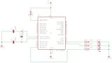
| Quote: |
#include "SPI with other PICS.h"
|
Thanks, I changed the file name but there's still no clock signal. But next time I will name it more properly |
|
|
Ttelmah
Joined: 11 Mar 2010
Posts: 19529
|
|
| Posted: Mon Jun 18, 2012 9:12 am |
|
|
I doubt if you would see the LED's light.
You are misunderstanding just how fast the byte will be. Even at the slowest /64 clock, on the 20MHz PIC, the byte will take under 1/10th of a mSec.....
Unless you have some incredibly old compiler, the CCS code runs fine, and has been used by thousands of people.
Best Wishes |
|
|
|
|
You cannot post new topics in this forum
You cannot reply to topics in this forum
You cannot edit your posts in this forum
You cannot delete your posts in this forum
You cannot vote in polls in this forum
|
Powered by phpBB © 2001, 2005 phpBB Group
|


