 |
 |
| View previous topic :: View next topic |
| Author |
Message |
matheuslps
Joined: 29 Sep 2010
Posts: 73
Location: Brazil


|
| AN889 and PPWM and sine table question. |
 Posted: Fri Sep 09, 2011 10:13 am Posted: Fri Sep 09, 2011 10:13 am |
 |
|
First of all, sorry for my english mistakes.
Let's begin....
So people, my graduating project is to develop a 3-phase inverter.
I started to study the application notes from microchip and it is very useful.
So, I have one question by now, reading the AN889, I read this:
"The value read from the sine table is scaled based on the motor frequency input. The sine table value is multiplied with the frequency input to find the PWM duty cycle and is loaded to the corresponding PWM duty cycle register."
So, I understood the use of the table. But why i need to scale the value and after that i put into the duty cycle register?
Why can not I just put the value directly into the duty value?
For example:
I have a table with 256 values (just an example). I use the CCS compiler.
On this compiler, I am using the PIC18F4431. It is very easy to configure 3 PWM channel and their complementaries and insert the dead-time. So, my table has 256 values from 9 to 240. In order the PPWM to work, I need to insert a value between 0 and 1. For example, for a 50% duty, I need to put 0.5. Ok. No problem.
My question is, why do I need to scale my table's values?
So, in meanwhile, I will continue my study.
Thanks |
|
 |
PCM programmer
Joined: 06 Sep 2003
Posts: 21708
|
|
| Posted: Fri Sep 09, 2011 1:43 pm |
|
|
I haven't done this type of motor controller, but I scanned the documents
and came up with this explanation:
The basic answer to your question is given on the first page of AN889,
on the right side of the page:
http://ww1.microchip.com/downloads/en/AppNotes/00889b.pdf
| Quote: |
VF CONTROL
A discussion of induction motor control theory is
beyond the scope of this document. We will mention
here only the salient points of VF control.
The base speed of the induction motor is directly
proportional to the supply frequency and the number of
poles of the motor. Since the number of poles is fixed
by design, the best way to vary the speed of the
induction motor is by varying the supply frequency.
The torque developed by the induction motor is directly
proportional to the ratio of the applied voltage and the
frequency of supply. By varying the voltage and the
frequency, but keeping their ratio constant, the torque
developed can be kept constant throughout the speed
range. This is exactly what VF control tries to achieve.
|
Then on page 3, it says:
| Quote: |
MOTOR DRIVE
The amplitude of phase voltage is determined by the
duty cycle of the PWM signals.
|
On page 5:
| Quote: |
A potentiometer connected to a 10-bit ADC channel
(AN1) determines the motor frequency. The microcontroller
uses the ADC results to calculate the PWM duty cycle and thus,
the frequency and the amplitude of the supply to the motor.
|
The sine table consists of 19 values (only), ranging from 0x00 to 0xFF.
It's at the end of the vf_control_with_7x7.asm file, in this zip file:
http://ww1.microchip.com/downloads/en/AppNotes/16f7x7vfmc.zip
So based on all this explanation, I think I can create a Torque formula:
Torque = K * V/F
K is some proportionality constant. It doesn't matter. If you want
to keep the Torque constant, then you have to keep the ratio of
Voltage to Frequency (V/F) constant. If you increase the motor speed
by increasing the PWM frequency, you must increase the voltage too.
The vf_control_with_7x7.asm file says this:
| Quote: | MOTOR FREQUENCY IS LIMITED BETWEEN 5Hz AND 60Hz.
|
So presumably, the Sine Table consists of values suitable for the lowest
expected PWM frequency of 5 Hz. (I don't know for sure).
If you want to run the motor faster, you increase the PWM frequency,
and so you have to multiply the sine table values to get a higher duty
cycle, which increases the motor voltage to keep V/F constant, and thus
keep the Torque constant over the speed range of the motor. |
|
|
matheuslps
Joined: 29 Sep 2010
Posts: 73
Location: Brazil
|
|
| Posted: Fri Sep 09, 2011 4:01 pm |
|
|
Thank you very much PCM Programmer!!!
Now I understood why I need to scale.
But i will tell you just one thing that I think that you understood wrong. You said:
| Quote: | | If you want to run the motor faster, you increase the PWM frequency... |
But in the page 5 on the AN889, we can read on the end of the last paragraph right before the Figure 5:
| Quote: | The frequency of the new PWM duty
cycle update determines the motor frequency, while the
value loaded in the duty cycle register determines the
amplitude of the motor supply. |
So, to change the motor speed, I change how fast the duty cycle is updated...
So, looking the figure right next this:
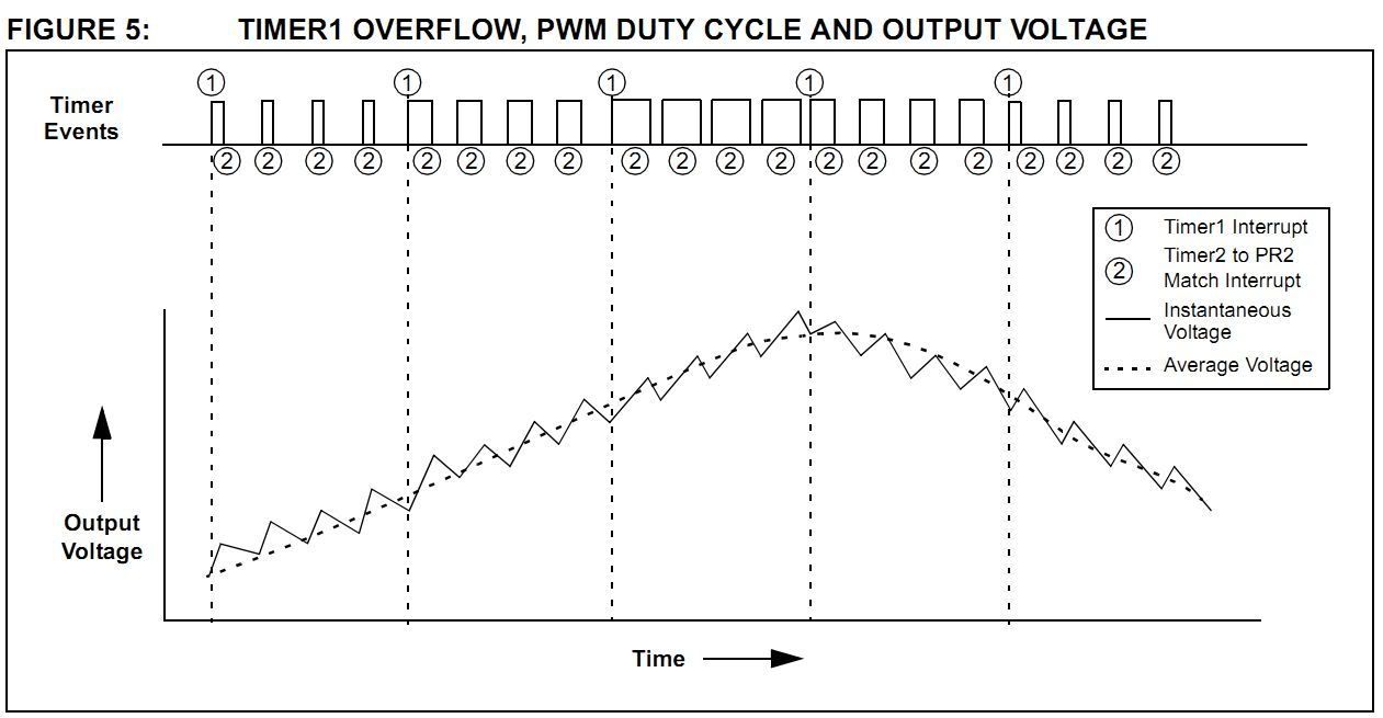
For example:
Imagine I running my motor with a duty cycle of 50%, if I want to speed it up, I need to adjust of the timer interrupt to overflow quickly and adjust the duty cycle in a proportional way, correct? Because maybe my sine table do not have the right duty, so I need to scale this....
So, what do you think? am I on the right direction now?
PS: I used an English dictionary on Firefox to not make spelling mistakes...
Bye |
|
|
PCM programmer
Joined: 06 Sep 2003
Posts: 21708
|
|
| Posted: Fri Sep 09, 2011 4:19 pm |
|
|
I just wanted to write up that one post. I didn't want to get any farther
involved in this. |
|
|
SherpaDoug
Joined: 07 Sep 2003
Posts: 1640
Location: Cape Cod Mass USA
|
|
| Posted: Fri Sep 09, 2011 4:52 pm |
|
|
This is getting pretty deep for discussion on a C compiler forum. Unless someone here has done this type of motor controller before, you really need to find a forum on motor control theory, or read some books, build some test hardware, and figure it out yourself.
This is more than just a software problem.
_________________
The search for better is endless. Instead simply find very good and get the job done. |
|
|
matheuslps
Joined: 29 Sep 2010
Posts: 73
Location: Brazil
|
|
| Posted: Fri Sep 09, 2011 6:18 pm |
|
|
Ok people, no problem...
I posted this same topic on the microchip forum but no replies for now...
Thanks by the way....
So, I have one question about the software that I am developing.....
A small test program where I have a sine table and update the duty cycle with the timer 1 interrupt.
In this peace of code, I need to put a value between 0 and 1 to get the right duty cycle. But my sine table has int8 values.
So, I just divided this values by 255 to get floats values to put into the PPWM formula.
My question is: If I want to avoid the task of divide the values by 255 and made a table only with the float points, is this will work?
Look my small test program. Here the PPWM is running at 1250Hz. What is the formula to calculate the frequency for the PPWM module?
And the configuration for the PPWM module that I am using is:
setup_power_pwm(PWM_FREE_RUN, 1, 0, POWER_PWM_PERIOD, 0, 1, 30);
The dead time is 30. But 30 what? 30 uS?
| Code: |
#include<18F4431.h>
#fuses HS, NOWDT, NOPROTECT, NOBROWNOUT, PUT, NOLVP
#use delay(clock=8000000)
#define POWER_PWM_PERIOD 1600
BYTE CONST SINE_WAVE[200] = {
128,132,136,139,143,147,150,154,158,161,165,169,172,176,179,
182,186,189,192,195,199,202,204,207,210,213,215,218,220,223,
225,227,229,231,233,235,237,238,240,241,242,243,244,245,246,
247,247,247,248,248,248,248,248,247,247,247,246,245,244,243,
242,241,240,238,237,235,233,231,229,227,225,223,220,218,215,
213,210,207,204,202,199,195,192,189,186,182,179,176,172,169,
165,161,158,154,150,147,143,139,136,132,128,124,120,117,113,
109,106,102,98,95,91,87,84,80,77,74,70,67,64,61,57,54,52,49,
46,43,41,38,36,33,31,29,27,25,23,21,19,18,16,15,14,13,12,11,
10,9,9,9,8,8,8,8,8,9,9,9,10,11,12,13,14,15,16,18,19,21,23,
25,27,29,31,33,36,38,41,43,46,49,52,54,57,61,64,67,70,74,77,
80,84,87,91,95,98,102,106,109,113,117,120,124};
BYTE sine_index;
float temp, temp1, temp2;
int8 x, y, z;
int1 aux;
#int_TIMER1 //Interrupção do Timer1
void temp1s(void) //Funcão. O que deverá ser feiro a cada interrupão.
{
if (aux == 0)
{
aux++;
if(++sine_index==200)
{
sine_index=0;
}
}
set_timer1 (30000); //Preload do Timer1
}
//=======================================
void main()
{
// Setup the 4 Power PWM channels as ordinary pwm channels.
setup_power_pwm_pins(PWM_COMPLEMENTARY,PWM_COMPLEMENTARY,PWM_COMPLEMENTARY,PWM_OFF);
// Mode = Free Run
// Postscale = 1 (1-16) Timebase output postscaler
// TimeBase = 0 (0-65355) Initial value of PWM Timebase
// Period = 2000 (0-4095) Max value of PWM TimeBase
// Compare = 0 (Timebase value for special event trigger)
// Compare Postscale = 1 (Postscaler for Compare value)
// Dead Time
setup_power_pwm(PWM_FREE_RUN, 1, 0, POWER_PWM_PERIOD, 0, 1, 30);
set_power_pwm0_duty((int16)((POWER_PWM_PERIOD *4) * .5)); // 10%
set_power_pwm2_duty((int16)((POWER_PWM_PERIOD *4) * .5)); // 40%
set_power_pwm4_duty((int16)((POWER_PWM_PERIOD *4) * .5)); // 60%
setup_timer_1 (T1_INTERNAL | T1_DIV_BY_8); //Configuração do Timer1 para clock interno = 1E6 dividido por 8
set_timer1 (30000); //Preload do Timer1
enable_interrupts(INT_TIMER1); //Habilita interrupção timer1
enable_interrupts(global); //habilita interrupcão global
while(1)
{
if (aux == 1)
{
x = SINE_WAVE[sine_index];
y = SINE_WAVE[sine_index+66];
z = SINE_WAVE[sine_index+132];
temp = x/255.0;
temp1 = y/255.0;
temp2 = z/255.0;
set_power_pwm0_duty((int16)((POWER_PWM_PERIOD *4) * temp));
set_power_pwm2_duty((int16)((POWER_PWM_PERIOD *4) * temp1));
set_power_pwm4_duty((int16)((POWER_PWM_PERIOD *4) * temp2));
aux++;
}
}
} |
I tried to make another table only with float points but I think it will not work:
| Code: | BYTE CONST SINE_WAVE_FLOAT[200] = {
0.50,0.52,0.53,0.55,0.56,0.58,0.59,0.60,0.62,0.63,0.65,0.66,0.67,0.69,0.70,
0.71,0.73,0.74,0.75,0.76,0.78,0.79,0.80,0.81,0.82,0.84,0.84,0.85,0.86,0.87,
0.88,0.89,0.90,0.91,0.91,0.92,0.93,0.93,0.94,0.95,0.95,0.95,0.96,0.96,0.96,
0.97,0.97,0.97,0.97,0.97,0.97,0.97,0.97,0.97,0.97,0.97,0.96,0.96,0.96,0.95,
0.95,0.95,0.94,0.93,0.93,0.92,0.91,0.91,0.90,0.89,0.88,0.87,0.86,0.85,0.84,
0.84,0.82,0.81,0.80,0.79,0.78,0.76,0.75,0.74,0.73,0.71,0.70,0.69,0.67,0.66,
0.65,0.63,0.62,0.60,0.59,0.58,0.56,0.55,0.53,0.52,0.50,0.49,0.47,0.46,0.44,
0.43,0.42,0.40,0.38,0.37,0.36,0.34,0.33,0.31,0.30,0.29,0.27,0.26,0.25,0.24,0.22,0.21,0.20,0.19,
0.18,0.17,0.16,0.15,0.14,0.13,0.12,0.11,0.11,0.10,0.09,0.08,0.07,0.07,0.06,0.06,0.05,0.05,0.05,0.04,
0.04,0.04,0.04,0.04,0.03,0.03,0.03,0.03,0.03,0.04,0.04,0.04,0.04,0.04,0.05,0.05,0.05,0.06,0.06,0.07,0.07,0.08,0.09,
0.10,0.11,0.11,0.12,0.13,0.14,0.15,0.16,0.17,0.18,0.19,0.20,0.21,0.22,0.24,0.25,0.26,0.27,0.29,0.30,
0.31,0.33,0.34,0.36,0.37,0.38,0.40,0.42,0.43,0.44,0.46,0.47,0.49}; |
How the best way to avoid the task of the division?
Thanks again!
Matheus Lopes. |
|
|
asmboy
Joined: 20 Nov 2007
Posts: 2128
Location: albany ny

|
|
|
matheuslps
Joined: 29 Sep 2010
Posts: 73
Location: Brazil
|
|
| Posted: Mon Sep 12, 2011 9:10 pm |
|
|
Thanks.
I will take a look on the page you sent me.
bye |
|
|
SherpaDoug
Joined: 07 Sep 2003
Posts: 1640
Location: Cape Cod Mass USA
|
|
| Posted: Tue Sep 13, 2011 7:06 am |
|
|
I would either write my own version of setup_power_pwm() that takes int8 inputs. Or I would locate the hardware register that sets the actual PWM duty cycle, which I am sure is an int register, and use setup_power_pwm() only to set things up and write my own routine to quickly set just the duty cycle register.
_________________
The search for better is endless. Instead simply find very good and get the job done. |
|
|
matheuslps
Joined: 29 Sep 2010
Posts: 73
Location: Brazil
|
|
| Posted: Tue Sep 13, 2011 1:02 pm |
|
|
Thanks SherpaDoug for your reply, but I am new, just one year learning CCS. I do not know how to write routines like this one that you mentioned.
bye |
|
|
|
|
You cannot post new topics in this forum
You cannot reply to topics in this forum
You cannot edit your posts in this forum
You cannot delete your posts in this forum
You cannot vote in polls in this forum
|
Powered by phpBB © 2001, 2005 phpBB Group
|

