| View previous topic :: View next topic |
| Author |
Message |
Andru-Khan
Joined: 08 Dec 2004
Posts: 4
Location: Israel


|
| PIC16F1946, high power consumption at sleep mode. |
 Posted: Sun Nov 28, 2010 4:58 pm Posted: Sun Nov 28, 2010 4:58 pm |
 |
|
Hi All,
I need to use PIC16F1946 in sleep mode for RTC operation but its power consumption is too high.
Even if I turn MCU to sleep mode immediately after start (no interrupts, no nothing) then it use about 85uA in sleep.
Please help to reduce consumption at sleep mode.
Here is the code for testing:
| Code: |
#include <16F1946.h>
#fuses INTRC_IO,NOWDT,NOMCLR,NOPUT,NOBROWNOUT,NOWDT,NOPROTECT,NOCPD,NOFCMEN,NOCLKOUT,NOWRT,NOVCAP,NOSTVREN,NOLVP,NODEBUG
#OPT 0
void main(void)
{
disable_interrupts(global);
sleep();
while(TRUE)
{
disable_interrupts(global);
sleep();
}
}
|
At the HW side I have 32KHz OSC connected to Timer1 (not in use at this the test) and the rest of the pins except ISP is not connected.
Compiler is PCM V4.110
Thanks,
Andrey... |
|
 |
PCM programmer
Joined: 06 Sep 2003
Posts: 21708
|
|
| Posted: Sun Nov 28, 2010 5:43 pm |
|
|
What amount of current do you measure in sleep mode ? What amount
is used during normal operating mode (i.e., when the PIC is running) ?
Describe all the external circuits on the board. What is the Vdd voltage
for the PIC and the board ? Post the part number of the voltage regulator
(if any), and its input voltage. Post the value of any pull-up resistors on
the board. Describe any circuits that might use power (Op-Amps,
sensors, Max232 chips, etc.). |
|
|
Andru-Khan
Joined: 08 Dec 2004
Posts: 4
Location: Israel
|
|
| Posted: Sun Nov 28, 2010 10:46 pm |
|
|
The amount of current in sleep mode (as I wrote previously): 85uA
The amount of current during normal operation mode: 3.71 mA
Vdd = 5V
Vbattery = 3V
No connection to the MCU except ISP (so 19K resistor connected between Vdd and Vpp is present) and OSC 32KHz connected to Timer1 (pins C0 and C1).
All the rest PINs are not connected.
No circuits that might use the power. |
|
|
PCM programmer
Joined: 06 Sep 2003
Posts: 21708
|
|
| Posted: Mon Nov 29, 2010 12:23 am |
|
|
| Quote: |
Vdd = 5V
Vbattery = 3V
No connection to the MCU except ISP (so 19K resistor connected between Vdd and Vpp is present) and OSC 32KHz connected to Timer1 (pins C0 and C1).
All the rest PINs are not connected.
No circuits that might use the power. |
Where does the 5v Vdd voltage come from ? Does it come from a
voltage regulator on the board ? If so, what's the manufacturer and
part number ? Or does the +5v come from a bench power supply ?
Where does the 3v Vbat come from ? From a lithium battery ? Where
is the +3v used on the board ? What chip is it connected to ? And what
pin number on the chip ? If this is some kind of battery backup circuit
for the PIC, and uses external schottky diodes to route the power, then
you need to describe the circuit or post a link to a schematic (for the
entire test circuit).
What is the OSC 32KHz ? Is it a watch crystal (and two capacitors) ?
I'm asking for a lot of details, but these details are what allow me and
others on this board to solve the problem. |
|
|
Andru-Khan
Joined: 08 Dec 2004
Posts: 4
Location: Israel
|
|
| Posted: Mon Nov 29, 2010 1:16 am |
|
|
All voltages came from a bench power supply: and 5V and 3V.
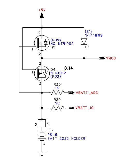
The schematic drawing of it please find below.
The current I'm measuring in sleep mode is the current that board taking from battery. The rest power source (+5V) is disconnected.
Also there are no other circuits that using Vmcu.
The OSC 32KHz is a watch crystal with 2 capacitors.
If MCU is removed then the board use 0 current.
And thank you very much for trying to help me. 
 |
|
|
PCM programmer
Joined: 06 Sep 2003
Posts: 21708
|
|
| Posted: Mon Nov 29, 2010 2:08 am |
|
|
1. Where do Vbat_ADC and Vbat_IO connect to ?
2. What is the #use delay() frequency for your program ?
3. What's the sequence of events in your testing of the sleep current ?
I assume that at some point, you manually turn off the +5v power.
-----------------------------
What I would do is this:
Build a new board. Put only the PIC on the board. Run the PIC at
+3.0v only. Don't include any external circuits on the board at all.
No 32 KHz crystal, no FETs, no diodes, no ADC, or any other chips, etc.
Then run your program. How much current does it use ? |
|
|
Andru-Khan
Joined: 08 Dec 2004
Posts: 4
Location: Israel
|
|
| Posted: Mon Nov 29, 2010 2:40 am |
|
|
1) Vbat_IO not connected (resistor R39 is not placed).
Vbat_ADC connected to analog input of MCU (PIN_A0).
2) In test application that I wrote in the beginning I do not use #use delay.
At the real application I use #use delay(clock=16000000).
3) The sequence is next:
a) Programming MCU with code written above.
b) Disconnect everything except +5V and +3V (for battery).
c) Manually disconnecting +5V.
d) Consumption is around 85uA...100uA.
Thanks. I'll update after the other tests. |
|
|
Ttelmah
Joined: 11 Mar 2010
Posts: 20054
|
|
| Posted: Mon Nov 29, 2010 3:23 am |
|
|
What you describe, implies you have the pins on the PIC _floating_. When the chip wakes up, all pins are in input mode. If you put a chip to sleep with pins floating, power consumption _will_ be high.
Basically when you sleep, _every_ pin, _must_ be driven. You either need external circuits/resistors pulling them to the rails, or pins must be set as outputs, and driven. The way you need to work, is to say 'what external circuits will be connected'. Then 'what levels do these need to turn them off'. Then 'what pins on the PIC will be driven by the external circuitry', and then finally, on all pins that are left floating, 'which rail can I drive them to, and draw least current'.
A floating pin, _will_ draw silly current. Repeat for multiple pins, and the chip will be drawing much more than expected....
Best Wishes |
|
|
|


