 |
 |
| View previous topic :: View next topic |
| Author |
Message |
kideltn
Joined: 08 Jun 2010
Posts: 13


|
| Pic 18f4550 interface SD card isn't working with lib ex_fat |
 Posted: Thu Jul 01, 2010 1:45 am Posted: Thu Jul 01, 2010 1:45 am |
 |
|
After simulation Proteus interface with SD card but fail | Code: | | http://www.ccsinfo.com/forum/viewtopic.php?t=42778 |
I think have problem in Proteus's simulation and decided to make a real circuit with 18f4550 interface SD card.
My SD card 64M,and formated FAT16.
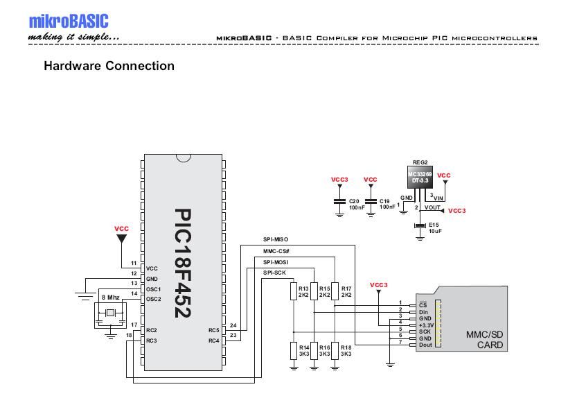
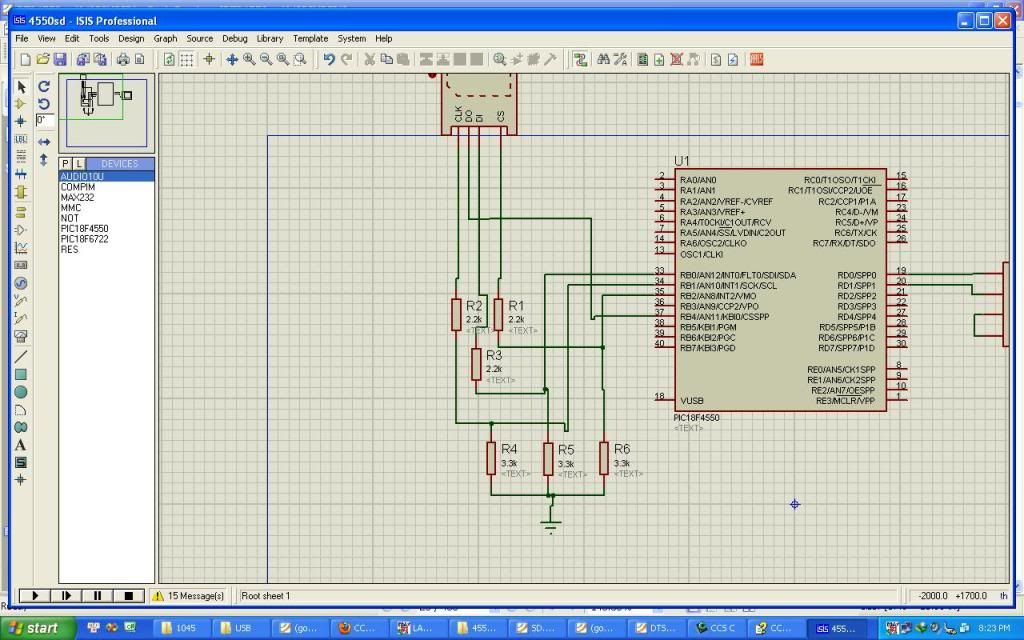
My portion shematic :

After chance the pin in ex_fat.c to match the pin 18f4550,I load hex on Pic.
Have many strange phenomenon appeared,it is although I didn't attach sd card on circuit,the command line still appear "OK"(I have inserted the code
| Code: | | if(i==GOODEC) printf("OK\r\n");//if installation success,printf OK |
at ex_fat.c to debug.
And when i attached sdcard,operated some command with it,ex:
The command line appear | Code: | | Making directory '/aaa/': |
and i can't operate the command line anymore.
I'm followed more topic about sdcard in CCSforum with lib ex_fat but still no answer.I hope to help from everyone.
Thanks alot ! |
|
 |
petiot
Joined: 28 Jun 2010
Posts: 5


|
|
 Posted: Thu Jul 01, 2010 8:12 am Posted: Thu Jul 01, 2010 8:12 am |
 |
|
| shouldn't your resistors on SDA and SCL pull up to not down? |
|
 |
Ttelmah
Joined: 11 Mar 2010
Posts: 19515


|
|
 Posted: Thu Jul 01, 2010 8:23 am Posted: Thu Jul 01, 2010 8:23 am |
 |
|
You need a level translator chip on the incoming data line from the SD card.
Given the minimum supply voltage for the 4550, is 4.2v, the voltage required for a 'high' on the SDI line, is 3.36v or more (if the supply voltage is higher). The SD card, only guarantees Voh to be the supply *0.75 (2.25v, with the 3v supply shown), the PIC is not going to see any 'high' data on this line....
Best Wishes |
|
 |
kideltn
Joined: 08 Jun 2010
Posts: 13


|
|
 Posted: Thu Jul 01, 2010 9:07 pm Posted: Thu Jul 01, 2010 9:07 pm |
 |
|
Thanks for reply !
I used schematic from

and change pin to match 18f4550.
I don't understand Ttelmah,
| Quote: |
You need a level translator chip on the incoming data line from the SD card.
Given the minimum supply voltage for the 4550 is 4.2v, the voltage required for a 'high' on the SDI line, is 3.36v or more (if the supply voltage is higher). The SD card, only guarantees Voh to be the supply *0.75 (2.25v, with the 3v supply shown), the PIC is not going to see any 'high' data on this line....
|
I think in SDI line the SD card understand logic but not PIC ?
And above divider resistor is true ? (in SDI,SCK,CS, the voltage after dividing is 5/5*3 = 3 V with SD card. In SDO, the PIC will read the logic high 3.3 V of SD card).
It is my idea, I'm not sure its right, and I hope many are helping, especially those who were successful with this project.
Thanks a lot ! |
|
 |
Ttelmah
Joined: 11 Mar 2010
Posts: 19515


|
|
 Posted: Fri Jul 02, 2010 2:10 am Posted: Fri Jul 02, 2010 2:10 am |
 |
|
The problem is voltage levels.
If you use a PIC that runs off 3.3v, and run both the PIC, and the SD card off this voltage, then both are using the same logic 'levels', and will co-exist fine. What you have is a PIC running off a higher voltage, and because of this it both outputs higher voltages than the SD card can take (easily handled with resistors), and wants higher voltage _inputs_ than the SD card generates. This later is not do-able with resistors, but instead needs a level translator of some sort. The 'logic levels' change with different voltage supplies.
Now, PIC inputs, have two different voltage levels required, according to whether you use 'Schmitt' inputs, or 'TTL' inputs. The Schmitt inputs, have a Vih specification, of 0.8*Vcc. So for a 5v supply, 4v is _required_ for a high to be seen. The TTL inputs have a specification at 5v, on the 18F452, of 2v required for Vih. A lot lower. It is possible to run without buffers, by using sofwtare SPI, on pins without the Schmitt inputs. However the circuit you show is not doing this, and won't actually work reliably.
A search here, will find many dozens of past posts about this. It is not a PIC/SD card 'thing', since using a low voltage PIC solves the problem, but a general 'mixing logic families of different voltages' thing. You wouldn't expect a piece of equipment designed for 220v, to run on 110v supplies without an adapter, and the same applies when you mix supplies on a PCB....
Best Wishes |
|
 |
kideltn
Joined: 08 Jun 2010
Posts: 13


|
|
 Posted: Fri Jul 02, 2010 7:50 am Posted: Fri Jul 02, 2010 7:50 am |
 |
|
Thanks you again!
Really, my major is coder and my project involved sd card. I'm beginner in electronic and thanks for your explanation to help me a lot.
I read datasheet 18f4550 and decide change pin as figure:

I changed SDO to RB4 (RB4 has input TTL).
But I really am not confident with above figure.
Can you consult me it !
Thanks a lot ! |
|
 |
Humberto
Joined: 08 Sep 2003
Posts: 1215
Location: Buenos Aires, La Reina del Plata


|
|
 Posted: Sun Jul 04, 2010 8:25 am Posted: Sun Jul 04, 2010 8:25 am |
 |
|
You need to add a 3-10K pull up (to +5V) in DO line.
Humberto |
|
 |
asmallri
Joined: 12 Aug 2004
Posts: 1634
Location: Perth, Australia


|
|
 Posted: Mon Jul 05, 2010 2:30 am Posted: Mon Jul 05, 2010 2:30 am |
 |
|
If you go to my projects page there are operational examples demonstrating how to integrate and SD card with a 5 volt PIC with resistor dividers on SDI, CLK and CS of the SD cards. For a production project you need a level translator between the DO of the Card and SPI of the PIC but for a proof of concept you will find it will work ok without it but the SPI PIC input will be operating out of spec. You also need the pullup to 3.3 volts on the DO of the card as already discussed.
While it is technically possible to implement a software SPI interface to the SD card as you have done, it is not generally a good idea. You need to take into account the shear volume of traffic that needs to be exchanged between the PIC and the SD card just to do a directory lookup.
_________________
Regards, Andrew
http://www.brushelectronics.com/software
Home of Ethernet, SD card and Encrypted Serial Bootloaders for PICs!!
Last edited by asmallri on Mon Jul 05, 2010 5:56 am; edited 1 time in total |
|
 |
ckielstra
Joined: 18 Mar 2004
Posts: 3680
Location: The Netherlands


|
|
 Posted: Mon Jul 05, 2010 3:38 am Posted: Mon Jul 05, 2010 3:38 am |
 |
|
Things become a lot easier when you use a PIC18 model that can run at 3.3V.
Why not use the PIC18LF4550? (L = Low voltage)
Or one of the many other PIC18 chips? |
|
 |
asmallri
Joined: 12 Aug 2004
Posts: 1634
Location: Perth, Australia


|
|
 Posted: Mon Jul 05, 2010 4:08 am Posted: Mon Jul 05, 2010 4:08 am |
 |
|
| ckielstra wrote: | Things become a lot easier when you use a PIC18 model that can run at 3.3V.
Why not use the PIC18LF4550? (L = Low voltage)
Or one of the many other PIC18 chips? |
One thing to consider if you are planning to use a file system is the RAM overhead required. I cannot talk to the CCS driver requirements (I do not know them) but here are the RAM requirements for ours:
RAM requirements: Standard Lite
File System overhead 560 560
Per File Overhead 540 38
Lite mode is a lower performance option but suited to limited RAM PICs. In general, I recommend using PICs with as much RAM as possible such as a PIC18F4620 with 3900 bytes of RAM or PIC18F46LF20 for a 3.3 volt version.
The PIC18F4550 if used with the USB gives you very little RAM for any real application if you want you application to support a FAT file system.
_________________
Regards, Andrew
http://www.brushelectronics.com/software
Home of Ethernet, SD card and Encrypted Serial Bootloaders for PICs!! |
|
 |
|
|
You cannot post new topics in this forum
You cannot reply to topics in this forum
You cannot edit your posts in this forum
You cannot delete your posts in this forum
You cannot vote in polls in this forum
|
Powered by phpBB © 2001, 2005 phpBB Group
|


