| View previous topic :: View next topic |
| Author |
Message |
pic2
Joined: 04 Nov 2009
Posts: 9


|
| pic12F675 pwm square wave is not so square |
 Posted: Wed Nov 04, 2009 4:49 pm Posted: Wed Nov 04, 2009 4:49 pm |
 |
|
Hello,
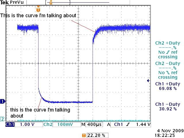
I wrote this program up to generate a pwm but the square wave is not so square when I view it on a scope from Pin_a1. What is it is the transition from on to off and off to on are not a square signal. They have a curve like a capacitor charge and discharge behaviors. Has anybody seen anything like this? My code is below. My compiler is PCWH V.3.249.
Thanks.
| Code: |
#include <12F675.h>
#device ADC=10
#fuses INTRC_IO,NOWDT,PUT,BROWNOUT,MCLR,PROTECT
//*********************** main routines *************
#use delay(clock=4000000)
void main()
{
long value;
long setpoint28=1024; // 28V from control input
long setpoint26=960; // 26V
long setpoint25=923; // 25V
long setpoint24=886; // 24V
long setpoint23=849; // 23V
long setpoint22=812; // 22V
long setpoint21=775; // 21V
long setpoint20=739; // 20V
long setpoint19=702; // 19V
long setpoint18=665; // 18V
long setpoint17=628; // 17V
long setpoint16=591; // 16V
long setpoint15=554; // 15V
long setpoint14=517; // 14V
long setpoint13=480; // 13V
long setpoint12=443; // 12V
long setpoint11=406; // 11V
long setpoint10=369; // 10V
long setpoint9=332; // 9V
long setpoint8=295; // 8V
long setpoint7=259; // 7V
long setpoint6=219; // 6V (was 221)
long setpoint5=185; // 5V
setup_adc_ports(sAN0|VSS_VDD); // set port AN0 pin 7 to analog input
setup_adc(ADC_CLOCK_DIV_8);
while(1)
{
set_adc_channel(0);
delay_us(10);
value=read_adc();
if (value<=setpoint6) // 0%
output_low(pin_a1);
if (value>setpoint24) // 70% of 5.2ms period
{ output_toggle(pin_a1);
delay_us(3640);
output_toggle(pin_a1);
delay_us(1560);
}
}
}
|
|
|
 |
PCM programmer
Joined: 06 Sep 2003
Posts: 21708
|
|
| Posted: Wed Nov 04, 2009 5:05 pm |
|
|
1. Describe the external circuit that is connected to Pin A1.
2. What oscilloscope are you using to measure the signal ?
3. Have you tested the scope on another signal, to be certain that
the problem is not in the scope ? |
|
|
pic2
Joined: 04 Nov 2009
Posts: 9
|
|
| Posted: Wed Nov 04, 2009 6:22 pm |
|
|
| PCM programmer wrote: | 1. Describe the external circuit that is connected to Pin A1.
|
pin A1 connected a pwm input pin on the LED driver p/n NUD4001 that drives series of 4 LEDs.
| wrote: |
2. What oscilloscope are you using to measure the signal ?
|
I used Tektronic TDS3032B.
| wrote: |
3. Have you tested the scope on another signal, to be certain that
the problem is not in the scope ? |
Yes, I tested it with another similar program written in ASM and it looked very sharp and square at ON and OFF transitions of the square wave on the same scope & same PCB. I only swapped out the PIC. |
|
|
PCM programmer
Joined: 06 Sep 2003
Posts: 21708
|
|
| Posted: Wed Nov 04, 2009 6:48 pm |
|
|
Why are you using output_toggle ? That requires reading the pin.
Why not just use output_high() and output_low(), as shown below:
| Quote: |
if (value>setpoint24) // 70% of 5.2ms period
{
output_high(pin_a1);
delay_us(3640);
output_low(pin_a1);
delay_us(1560);
}
}
|
|
|
|
pic2
Joined: 04 Nov 2009
Posts: 9
|
|
| Posted: Wed Nov 04, 2009 7:06 pm |
|
|
In my prior version of the posted codes, I did use output_high(pin_a1) & output_low(pin_a1) but it was the same. Could it be different if I use timer 0, or timer 1 for the delay? The reason I say so is that I do not know how to use timer0 or timer0 for delay with PIC12F675. I am fairly new to pic.
By the way, thank you very much for responding to my post PCM programmer. |
|
|
PCM programmer
Joined: 06 Sep 2003
Posts: 21708
|
|
| Posted: Wed Nov 04, 2009 7:11 pm |
|
|
Disconnect the NUD4001 chip from the PIC, and look at the PIC pin
with your oscilloscope. Does the signal now look good ? |
|
|
pic2
Joined: 04 Nov 2009
Posts: 9
|
|
| Posted: Wed Nov 04, 2009 7:18 pm |
|
|
| I'll do that and let you know tomorrow. Thanks. |
|
|
pic2
Joined: 04 Nov 2009
Posts: 9
|
|
| Posted: Wed Nov 04, 2009 8:08 pm |
|
|
Hello PCM Programmer,
I just revised the code, ran it with standalone PIC without any other circuitry or pcb, and measured the signal right off pin A1. Please look at the image below to see the curve I'm talking about.
This is the revised code:
| Code: |
if (value>setpoint24) // 70% of 5.2ms period
{ output_high(pin_a1);
delay_us(3640);
output_low(pin_a1);
delay_us(1560);
}
|
 |
|
|
mutthunaveen
Joined: 08 Apr 2009
Posts: 100
Location: Chennai, India
|
| what u r using to plot this |
| Posted: Wed Nov 04, 2009 9:52 pm |
|
|
hi...... sorry for asking now I mean here 
Please tell me that how and what software u r using to plot such type of graphs..... please bro. I am using the PC oscilloscope based on microphone input.
Please tell me the software name and hardware diagram u r using.
If u feel hard to reply this please send it to this mail ID "mutthunaveen@gmail.com"
please bro......  |
|
|
dyeatman
Joined: 06 Sep 2003
Posts: 1934
Location: Norman, OK
|
|
| Posted: Thu Nov 05, 2009 7:18 am |
|
|
Pic2,
That graph looks like an uncalibrated scope probe or capacitance on the PIC pin to me. High frequency rolloff like that is characteristic of scope probe capacitance issues.
Try connecting it to your calibration point and verify it is perfectly square to determine if the probe(s) are to blame.
If the probes are good I can't imagine any possible way that code can cause something like that so I think it would be hardware related (chip or circuit).
_________________
Google and Forum Search are some of your best tools!!!! |
|
|
pic2
Joined: 04 Nov 2009
Posts: 9
|
|
| Posted: Thu Nov 05, 2009 11:42 am |
|
|
dyeatman,
Thanks bros. I switched to another scope and it looks nice and neat. I checked the scope with not so square signal at the probe comp. port and it did show the same "not so square" behavior as well.
see below,
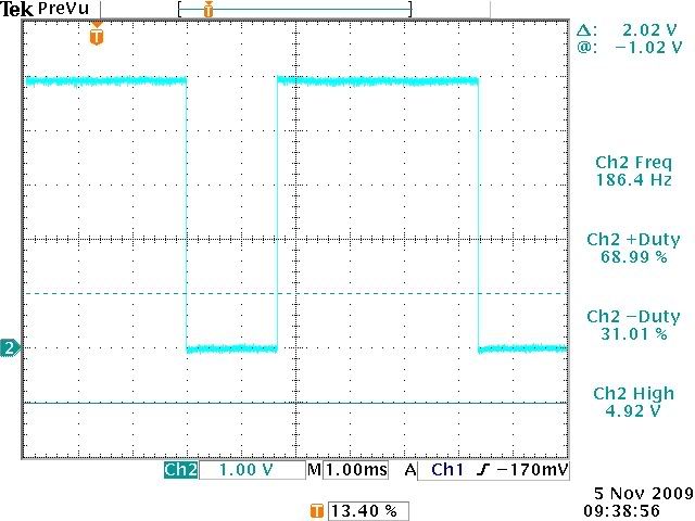
Thanks everybody for replying to my message.
mutthu,
I used tektronic scope and capture the plot right off the scope with floppy disk! It is not pc base. |
|
|
bkamen
Joined: 07 Jan 2004
Posts: 1615
Location: Central Illinois, USA
|
|
| Posted: Thu Nov 05, 2009 3:17 pm |
|
|
Ahhh yes, always watch those uncalibrated probes!
You should be able to adjust them back to square.
All my HP/Agilent probes come with a screwdriver to tweak the probe's trimmer caps.
If you haven't checked into it yet, you might want to.
_________________
Dazed and confused? I don't think so. Just "plain lost" will do. :D |
|
|
dyeatman
Joined: 06 Sep 2003
Posts: 1934
Location: Norman, OK
|
|
| Posted: Thu Nov 05, 2009 4:26 pm |
|
|
bkamen is absolutely correct. There is a trimmer on each probe.
Connect the probe to the calibration point and adjust the trimmer to
eliminate the rolloff in the square wave.
_________________
Google and Forum Search are some of your best tools!!!! |
|
|
Guest
|
|
| Posted: Thu Nov 05, 2009 6:21 pm |
|
|
| It was the probe issue. Thanks for the tips guys. I'll do it. |
|
|
|


