 |
 |
| View previous topic :: View next topic |
| Author |
Message |
Grimmjow
Joined: 15 Apr 2009
Posts: 10


|
| problem w/ ltc2440 A/D and pic16f877 interface |
 Posted: Wed Apr 15, 2009 12:12 pm Posted: Wed Apr 15, 2009 12:12 pm |
 |
|
Hi there!!
I'm dealing w/ how to interface the ltc2440 A/D w/ pic16f877 by using the spi commands. I cannot find what's wrong w/ my code and I'm dealing with it for almost two full days  Code is below: Code is below:
| Code: | #include <16f877.h>
#fuses XT,NOPUT,NOWDT,NOPROTECT,NOLVP,BROWNOUT
#define use_portb_lcd TRUE
#use delay (clock=4M)
#include <lcd.c>
#define SPI_MODE_0 (SPI_L_TO_H | SPI_XMIT_L_TO_H)
#define SPI_MODE_1 (SPI_L_TO_H)
#define SPI_MODE_2 (SPI_H_TO_L)
#define SPI_MODE_3 (SPI_H_TO_L | SPI_XMIT_L_TO_H)
#define _CS PIN_D0 //select ADC
#define BUSY PIN_D1
#byte SSPSTAT=0x94
#byte SSPCON=0x14
#bit CKE=SSPSTAT.6
#bit CKP=SSPCON.4
int SampRateADC=0x78; //sampling rate is selected as 6.875Hz
struct fourbytes
{
int8 te0;
int8 te1;
int8 te2;
int8 te3;
};
union
{
signed int32 bits32;
struct fourbytes by;
} voltage;
float temperature;
void initialize(void);
void ReadADC(void);
void show(void);
void main()
{
initialize();
while(true) {
output_low(_CS);
while(input(BUSY)){};
ReadADC();
//getdatabytes();
output_high(_CS);
voltage.bits32 = (voltage.bits32>>5)&(0b00000000111111111111111111111111);
temperature=(float)voltage.bits32;
temperature=temperature*0.17881393*0.001; //turned into analog
show();
}
}
void initialize(){
lcd_init();
delay_ms(6);
setup_spi(SPI_MASTER | SPI_MODE_1 | SPI_CLK_DIV_4);
output_bit(CKP,0); //data at rising edge
output_bit(CKE,1);
}
void ReadADC(){
spi_write(SampRateADC);
while(!spi_data_is_in()){};
voltage.by.te3=spi_read();
spi_write(SampRateADC);
while(!spi_data_is_in()){};
voltage.by.te2=spi_read();
spi_write(SampRateADC);
while(!spi_data_is_in()){};
voltage.by.te1=spi_read();
spi_write(SampRateADC);
while(!spi_data_is_in()){};
voltage.by.te0=spi_read();
}
void show(){
lcd_gotoxy(1,1);
printf(lcd_putc,"\f temperature is = \n %f Celcius",temperature);
delay_ms(2);
} |
Resulting pulses are also in the link below:
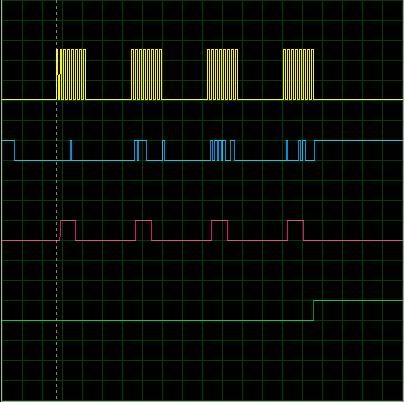
yellow-> SCK;
blue->SDI;
red->SDO;
green->busy.
Problem here is, I cannot get a constant data. When I try to see the result in the LCD, I see 5-6 different results instead of one result. In other words, SDI is not stable!! I think I cannot synchronize the data stream in the ReadADC(). I don't know built-in spi functions very well.
Any help would be appreciated  |
|
 |
PCM programmer
Joined: 06 Sep 2003
Posts: 21708
|
|
| Posted: Thu Apr 16, 2009 12:59 am |
|
|
| Quote: | setup_spi(SPI_MASTER | SPI_MODE_1 | SPI_CLK_DIV_4);
output_bit(CKP,0); //data at rising edge
output_bit(CKE,1); |
The LTC2440 operates in SPI Mode 0. You should get rid of the lines
above and use the following code:
| Code: | | setup_spi(SPI_MASTER | SPI_MODE_0 | SPI_CLK_DIV_4); |
Note that the CKP and CKE lines are removed.
| Quote: | void ReadADC(){
spi_write(SampRateADC);
while(!spi_data_is_in()){};
voltage.by.te3=spi_read();
etc.
|
Your ReadADC() code is too complex and doesn't match the sample
CCS code in their AN96 appnote. See page 14 of the appnote.
It should be done like this:
| Code: |
void ReadADC()
{
voltage.by.te3=spi_read(SampRateADC);
voltage.by.te2=spi_read(0);
voltage.by.te1=spi_read(0);
voltage.by.te0=spi_read(0);
} |
| Quote: | #define BUSY PIN_D1
while(input(BUSY)){}; |
In their sample code, and in the data sheet, they want you to poll the
SDI pin on the PIC. The #define BUSY statement should be changed to
use pin C4.
AN96 can be downloaded from this page:
http://www.linear.com/pc/productDetail.jsp?navId=H0,C1,C1155,C1001,C1152,P1771
Regarding external the connections:
Make sure you have a stable reference voltage connected to the REF+
pin on the LTC2440. It's probably easiest to connect it to the Vdd
voltage. Connect the REF- pin to ground.
Also make sure the \EXT pin on the LTC2440 is connected to ground.
I didn't look at your math code. I would just try to display the raw
value received from the ADC for the initial tests. Display it as a
32-bit hex value every 500 ms. Then if that works, add your math code. |
|
|
Grimmjow
Joined: 15 Apr 2009
Posts: 10
|
|
| Posted: Thu Apr 16, 2009 12:34 pm |
|
|
First of all, thanks for the quick reply
I did everything that you said to me PCM programmer...My new code looks like;
| Code: | #include <16f877.h>
#fuses XT,NOPUT,NOWDT,NOPROTECT,NOLVP,BROWNOUT
#define use_portb_lcd TRUE
#use delay (clock=4M)
#include <lcd.c>
#define SPI_MODE_0 (SPI_L_TO_H | SPI_XMIT_L_TO_H)
#define SPI_MODE_1 (SPI_L_TO_H)
#define SPI_MODE_2 (SPI_H_TO_L)
#define SPI_MODE_3 (SPI_H_TO_L | SPI_XMIT_L_TO_H)
#define _CS PIN_D0
#define BUSY PIN_C4
#byte SSPSTAT=0x94
#byte SSPCON=0x14
#bit CKE=SSPSTAT.6
#bit CKP=SSPCON.4
int SampRateADC=0x78;
struct fourbytes
{
int8 te0;
int8 te1;
int8 te2;
int8 te3;
};
union
{
signed int32 bits32;
struct fourbytes by;
} voltage;
float temperature;
void initialize(void);
void ReadADC(void);
void show(void);
void main()
{
initialize();
while(true) {
output_low(_CS);
while(input(BUSY)){};
ReadADC();
output_high(_CS);
show();
}
}
void initialize(){
lcd_init();
delay_ms(6);
setup_spi(SPI_MASTER | SPI_MODE_0 | SPI_CLK_DIV_4);
}
void ReadADC(){
voltage.by.te3=spi_read(SampRateADC);
voltage.by.te2=spi_read(0);
voltage.by.te1=spi_read(0);
voltage.by.te0=spi_read(0);
}
void show(){
lcd_gotoxy(1,1);
printf(lcd_putc,"\f temperature is = \n %LX Celcius",voltage.bits32);//temperature);
delay_ms(500);
} |
According to these, my pulses changed as;
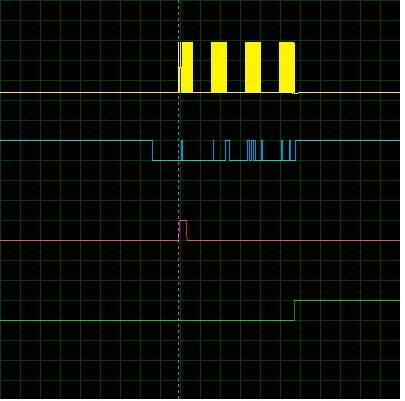
but still, same problem exists.
I don't think there is something wrong w/ the code. Therefore, I will have few questions:
1) You said that "In their sample code, and in the data sheet, they want you to poll the
SDI pin on the PIC. The #define BUSY statement should be changed to
use pin C4. "
Then what does the "busy" pin stands for?? Also, when I do it with either pin_d1 or pin_c4, I get pretty much the same result:sad:
2) Now, I'm wondering whether my hardware is right or wrong. So; my connections are:
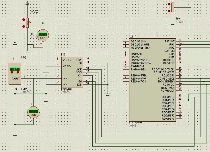
Could you tell me is there a mistake?? B/c I have to do this as soon as possible in order to enhance this project.
Thanks again |
|
|
PCM programmer
Joined: 06 Sep 2003
Posts: 21708
|
|
| Posted: Thu Apr 16, 2009 1:25 pm |
|
|
| Quote: | | Then what does the "busy" pin stands for?? |
The BUSY signal is only used if the EXT pin is tied high.
The LTC2440 data sheet says:
| Quote: |
If EXT is tied high, the internal serial clock mode is selected.
The device generates its own SCK signal and outputs this on
the SCK pin. A framing signal BUSY (Pin 15) goes low indicating
data is being output. |
You are using external SCK (generated by the PIC), and the
EXT pin is tied low for this mode. So BUSY is not used in your design.
You are using a simulator, so we don't know if the simulator has
bugs in the LTC2440 simulation.
You're missing the crystal, its capacitors, and the MCLR pull-up
resistor on the PIC. Is this allowed by the simulator ?
Initially, try setting VREF+ to the same as the Vdd voltage (+5v). |
|
|
Grimmjow
Joined: 15 Apr 2009
Posts: 10
|
|
| Posted: Thu Apr 16, 2009 5:51 pm |
|
|
First of all, thanks for the explanation about the BUSY pin...Things are a bit more clear now..
| Quote: | You are using a simulator, so we don't know if the simulator has
bugs in the LTC2440 simulation. |
Yes, you're right...But the simulator that I'm using has only one 24-bit ADC. So, I have to rely on it for the time-being.
| Quote: | You're missing the crystal, its capacitors, and the MCLR pull-up
resistor on the PIC. Is this allowed by the simulator ? |
Yes, simulator allows this sort of things. These are not problem in virtual world...
I disconnected the BUSY pin, and tried again but nothing has changed.
The real problem that I'm dealing w/ is; I don't want to set/clear every single bit(therefore switch) in the pic manually(like I did in the previous code such as CKE,CKP etc.) in order to communicate through spi. I wanna use and understand the built-in functions of the CCS-C. Otherwise, I would use assembly.
If I cannot communicate via these built-in functions, I'll most probably start to use fast_io and program bit-by-bit. But then, as I said before, what's the meaning of using CCS-C if you cannot utilize these flexibilities??
If you still have any ideas or suggestions, I would really appreciate it Otherwise, I would start to write the code with a new point of view which I do not prefer  |
|
|
PCM programmer
Joined: 06 Sep 2003
Posts: 21708
|
|
| Posted: Thu Apr 16, 2009 6:01 pm |
|
|
| Post your compiler version. |
|
|
Grimmjow
Joined: 15 Apr 2009
Posts: 10
|
|
| Posted: Fri Apr 17, 2009 9:44 am |
|
|
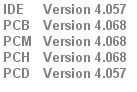
Here is the version:
 |
|
|
PCM programmer
Joined: 06 Sep 2003
Posts: 21708
|
|
| Posted: Fri Apr 17, 2009 11:31 am |
|
|
| Quote: | void show(){
lcd_gotoxy(1,1);
printf(lcd_putc,"\f temperature is = \n %LX Celcius",voltage.bits32);//temperature);
delay_ms(500);
} |
Post some of the values that are displayed by the printf statement. |
|
|
Grimmjow
Joined: 15 Apr 2009
Posts: 10
|
|
| Posted: Fri Apr 17, 2009 11:46 am |
|
|
Some of the values are:
02415C44
22415C04
22015C04
22015844
20015044
20414044
20414444
22410C44
22400C40
02401C40
After this sequence, it starts all over again. This is for Vin=0.21V for Vref=3V. So, range is +-1.5V. For every voltage, it has this kind of voltage sequence instead of having a single value.
By the way, there is no math code applied.
Thanks a lot again... |
|
|
PCM programmer
Joined: 06 Sep 2003
Posts: 21708
|
|
| Posted: Fri Apr 17, 2009 1:09 pm |
|
|
I would simplify the test environment. Get rid of the LM35 temperature
sensor, and connect the VIN+ pin of the LTC2440 to ground.
Also, don't use a Vref that is lower than the Vcc of the LTC2440.
The schematic doesn't show the Vcc pin. I assume it's set to +5v.
If so, set VREF+ to +5v. Then run the test and post the output again. |
|
|
Grimmjow
Joined: 15 Apr 2009
Posts: 10
|
|
| Posted: Fri Apr 17, 2009 2:30 pm |
|
|
I did exactly what you said. BTW; yes Vcc is set to 5V.
Here are the results:
037E0F78
077E1F78
077C1F70
0F783F62
1F787F66
1F717F46
1F637F0E
1F637E1E
1F477C1E
1F0F7C3E
1E1F787E
1C1F717E
1C3F737E
187F637E
117F477C
137F0F7C
Now, data starts repeating...Ok, now I'm confused  At first data set, there was ten data...Now there is sixteen. In other words, as range increased; number of repeating data increased as well. At first data set, there was ten data...Now there is sixteen. In other words, as range increased; number of repeating data increased as well.
Thanks again for your help... |
|
|
PCM programmer
Joined: 06 Sep 2003
Posts: 21708
|
|
| Posted: Fri Apr 17, 2009 3:15 pm |
|
|
It runs continuously, displaying the output every 500 ms.
If you run it for 8 seconds, you get 16 numbers out.
I'm not sure what else I can do. I think your current code looks close
to their sample code in AN96. I begin to suspect the simulation of the
LTC2440 has a problem. I can't do anything about that. |
|
|
Grimmjow
Joined: 15 Apr 2009
Posts: 10
|
|
| Posted: Fri Apr 17, 2009 4:33 pm |
|
|
Ok; thanks a lot for your effort...
If(or when) I solve the problem; I will post it for the next generations  |
|
|
Grimmjow
Joined: 15 Apr 2009
Posts: 10
|
|
| Posted: Tue Apr 21, 2009 6:46 am |
|
|
I started to doubt that simulator has bug with the ltc2440 model. So, i tried pretty much the same code with ltc1864(16-bit ADC with spi).
Code is as follows:
| Code: | #include <16f877.h>
#fuses XT,NOPUT,NOWDT,NOPROTECT,NOLVP,BROWNOUT
#define use_portb_lcd TRUE
#use delay (clock=4M)
#include <lcd.c>
#define SPI_MODE_0 (SPI_L_TO_H | SPI_XMIT_L_TO_H)
#define SPI_MODE_1 (SPI_L_TO_H)
#define SPI_MODE_2 (SPI_H_TO_L)
#define SPI_MODE_3 (SPI_H_TO_L | SPI_XMIT_L_TO_H)
#define CONV PIN_D0
int8 MSB;
int8 LSB;
int16 data;
void initialize(void);
void ReadADC(void);
void show(void);
void main()
{
initialize();
while(True){
ReadADC();
delay_us(50);
show();
}
}
void initialize(){
output_low(CONV);
lcd_init();
delay_ms(6);
setup_timer_2(T2_DIV_BY_16,124,1); // timer is 500 Hz
setup_spi(SPI_MASTER | SPI_MODE_3 | SPI_CLK_T2);
}
void ReadADC(){
output_high(CONV);
delay_us(30);
output_low(CONV);
MSB=spi_read(0);
LSB=spi_read(0);
data=make16(MSB,LSB);
}
void show(){
lcd_gotoxy(1,1);
printf(lcd_putc,"\f Data is = \n %LX Hex",data);
delay_ms(2);
} |
This code works in simulator w/ ltc1864 without any problem. Therefore, i decided to quit trying it with ltc2440 since I may be dealing with a buggy model
I believe this may enlight some people who may have encountered with the same problem... |
|
|
|
|
You cannot post new topics in this forum
You cannot reply to topics in this forum
You cannot edit your posts in this forum
You cannot delete your posts in this forum
You cannot vote in polls in this forum
|
Powered by phpBB © 2001, 2005 phpBB Group
|

