| View previous topic :: View next topic |
| Author |
Message |
rb8720
Joined: 04 Jun 2007
Posts: 13


|
| detect potentiometer change on output pin. |
 Posted: Wed Jul 30, 2008 2:30 pm Posted: Wed Jul 30, 2008 2:30 pm |
 |
|
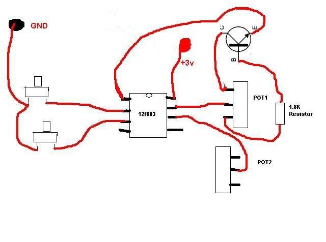
Can anyone tell me how you would detect a change in the potentiometer in this circuit. Pins 2 and 3 are connected to tact switches that are connected to ground. 6 and 7 are connected to the wiper of the left and right pots. and 4 and 5 are not used. Pin 1 is connected to +3v and Pin 8 is connected to a transistor connected to the pot. What i don't understand is if you only have 1 pin connected to the pot and it is used for output how do you detect if the pot is turned? The pot is actually the trigger on a xbox controller. The chip is designed to make the contrller rapid fire when the trigger is pulled. Under normal operation when the trigger is pulld the middle leg is taken low which fires the trigger. so for the chip to make it rapid fire the out put pin ( pins 6 and 7 ) must toggle between High and low ( or tri state) to simulate the triggre being pulled and released rapidly. the buttons connected to pins 2 and 3 toggle the chip operation from doing nothing to rapidfire. So if pins 6 and 7 atre output and 2 and 3 are ot connected to the triggers. How does the chip detect when the triggers are pulled. Can you read adc and output on the same pin at the same time? Here is a very rough drawing of the circuit.
RB8720
 |
|
 |
Ttelmah
Guest
|
|
| Posted: Thu Jul 31, 2008 10:06 am |
|
|
You can switch pins between being inputs, outputs, and ADC inputs, pretty quickly. As shown, there is no way to detect the setting of pot2. However, I'd guess that the real circuit has some differences. Possibly something as simple as an unconnected length of track connected to one end of the pot, routing close to something else. The understanding, will be in small details like this.
Best Wishes |
|
|
SherpaDoug
Joined: 07 Sep 2003
Posts: 1640
Location: Cape Cod Mass USA
|
|
| Posted: Thu Jul 31, 2008 11:48 am |
|
|
The connection of Pot 1 and the transistor doesn't make any sense to me either. Something is wrong somewhere.
_________________
The search for better is endless. Instead simply find very good and get the job done. |
|
|
Humberto
Joined: 08 Sep 2003
Posts: 1215
Location: Buenos Aires, La Reina del Plata
|
|
| Posted: Thu Jul 31, 2008 3:16 pm |
|
|
The quasi-circuit shown does not have any sense.
...Pin 1 should be +Vdd
...Pin 8 should be Gnd
...hence the transistor should be a P type...
...hence all is wrong.
Humberto |
|
|
|


