 |
 |
| View previous topic :: View next topic |
| Author |
Message |
bulut_01
Joined: 24 Feb 2024
Posts: 62


|
|
 Posted: Sat Mar 09, 2024 6:42 pm Posted: Sat Mar 09, 2024 6:42 pm |
 |
|
| temtronic wrote: | so.. what's stored in the array called 'bitmap'
and
you still haven't deleted the CCS driver in your previous post !!!
If you don't do that soon, you'll be in trouble with the forum !!! |
| Code: | void SSD1306_ROMBMP(uint8_t x, uint8_t y, rom uint8_t *bitmap, uint8_t w, uint8_t h)
{
for( uint16_t i = 0; i < h/8; i++ )
{
for( uint16_t j = 0; j < (uint16_t)w * 8; j++)
{
if(bit_test(wifi[j/8 + i*w], j % 8) == 1)
SSD1306_DrawPixel(x + j/8, y + i*8 + (j % 8),1);
else
SSD1306_DrawPixel(x + j/8, y + i*8 + (j % 8),1);
}
}
} |
wifi |
|
 |
bulut_01
Joined: 24 Feb 2024
Posts: 62
|
|
| Posted: Sun Mar 10, 2024 8:00 am |
|
|
| Is there anyone who can help with this? |
|
|
Ttelmah
Joined: 11 Mar 2010
Posts: 19238
|
|
| Posted: Sun Mar 10, 2024 8:22 am |
|
|
Put simply no.
The code as posted in incomprehensible. You need to document what it is
meant to do, and how you think it works. I look at it and cannot easily
work out what the relationship is between what byte you have and what
pixel you want to set from it.
I have a standard rule with students, that any code that has less than
50% comments will automatically be rejected. Also make your variables
have meaningful names. So start_xcoord, width, height, etc..
The more you create documentation and self documentation in your code,
the easier it will be for yourself to understand, as well as others. |
|
|
temtronic
Joined: 01 Jul 2010
Posts: 9120
Location: Greensville,Ontario
|
|
| Posted: Sun Mar 10, 2024 9:46 am |
|
|
The huge problem, I finally see, is that he's mixing code from at least TWO 'GLCD drivers'.
As to getting the code to work....go back to pencil and paper, play 'computer' and write down what's happening line by line....pixel by pixel....
In effect YOU become the simulator for the PIC ! |
|
|
Ttelmah
Joined: 11 Mar 2010
Posts: 19238
|
|
| Posted: Sun Mar 10, 2024 10:13 am |
|
|
I think he it trying to walk through bytes in the rom array, and set/clear
pixels based on whether the bits are on. However the maths of this
'walk' is completely unclear. I think you or I jay, would use a simple
bitmask and rotation to do this. Certainly quicker.
It is made worse, since the sizes he specifies are not multiples of the
byte size. I suspect this is actually why his result doesn't work. He also
draws the pixel the same whether the bit is set or not. I'd have expected
one of the draws to have a 0 rather than a 1, to clear the pixel. |
|
|
bulut_01
Joined: 24 Feb 2024
Posts: 62
|
|
| Posted: Sun Mar 10, 2024 12:24 pm |
|
|
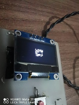
I think I explained it enough above. I want to draw something on the screen. I print the ready-made ROM data I have on the screen without any problems. But when I draw the data I drew on the https://lopaka.app/ site, nonsense things appear on the screen. I cannot understand why.
| Code: | unsigned int8 wi[] = {
0x80,0x0f,0x00,0x60,0x30,0x00,0x18,0xc0,0x00,0x84,0x0f,0x01,0x62,0x30,0x02,0x11,
0x40,0x04,0x0a,0x87,0x02,0xc4,0x1f,0x01,0xe8,0xb8,0x00,0x70,0x77,0x00,0xa0,0x2f,
0x00,0xc0,0x1d,0x00,0x80,0x0a,0x00,0x00,0x07,0x00,0x00,0x02,0x00,0x00,0x00,0x00
}; |
| Code: | void SSD1306_ROMBMP(unsigned int8 x, unsigned int8 y, unsigned int16 w, unsigned int16 h, rom unsigned int16 *bitmap)
{
for(unsigned int16 i = 0; i < h/8; i++)
{
for(unsigned int16 j = 0; j < w * 8L; j++)
{
if(bit_test(wi [j/8 + i*w], j % 8) == 1)
oled_Pixel (x + j/8, y + i*8 + (j % 8),1);
else
oled_Pixel(x + j/8, y + i*8 + (j % 8),0);
}
}
} |
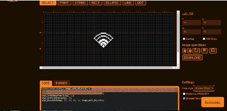
Normally, I should see a graph like the one on this screen, but a ridiculous graph is created.
This is okay to try a different ROM code.
 |
|
|
temtronic
Joined: 01 Jul 2010
Posts: 9120
Location: Greensville,Ontario
|
|
| Posted: Sun Mar 10, 2024 2:15 pm |
|
|
I suspect your 'wifi icon' data is not in the correct 'format' to be displayed.
For graphics, I get a large piece of 8 x 8 graph paper, fill in the 'pixels' to make the design. Now decode the rows and columns of pixels into the correct binary '1' for on, '0' of off ,group into bytes,convert into hex data for the computer to then translate and send to the GLCD.
It may be that the online program(app) you used is for a specific GLCD.Not all are the same. Maybe the starting location of 1,1 instead of 0,0, # of pixels per row, # of pixels per column, ??? I don't use that GLCD so no datasheet to see what is required to get a pixel to be on or off. |
|
|
bulut_01
Joined: 24 Feb 2024
Posts: 62
|
|
| Posted: Sun Mar 10, 2024 2:40 pm |
|
|
| Someone is running Ardinuo in this format. The rombmp algorithm draws incorrectly, although I tried hard, I could not solve the problem. https://lopaka.app/ The rom code created on this site works with SSD1306. There is an example with Ardinuo. I cannot draw it correctly in my own circuit. |
|
|
temtronic
Joined: 01 Jul 2010
Posts: 9120
Location: Greensville,Ontario
|
|
| Posted: Sun Mar 10, 2024 5:21 pm |
|
|
curious so I looked more into this...
the GLCD is 128 bits wide by 64 bits tall, Since array data is stored in bytes, so I see it as 16 bytes wide by 8 bytes tall. 128 bytes for a screen.
your 'wifi' array is 16 bytes wide by 3 bytes tall, so just the first 3 lines of 8 lines. 48 bytes of data out of 128 bytes
the 'wifi graphic is 'square' in the online applications program
If a set bit in the data array means the pixel is 'on' and white, then the first data 0x80 should put the first pixel on in first line. The wifi graphic shows that as off/dark. So there is a 'translation' problem.
1st. I don't know how the online app created the data array
2nd. The graphic is square is shape
3rd, There should be 8 lines of 16 bytes for the graphic
4th The best 'square' of pixel data would be 7 bytes wide x 7 bytes tall
you will have to find the source code for the online app or at least HOW it maps the pixels. I'm old skool, use graph paper, every square is a pixel,make the graphic, code the binary, then convert to hex.Takes maybe 1/2hr per graphic to code. The more you do the faster you get.
Sorry I don't have that GLCD so I can't cut code to test. |
|
|
bulut_01
Joined: 24 Feb 2024
Posts: 62
|
|
| Posted: Sun Mar 10, 2024 10:58 pm |
|
|
In the link I gave, they design the screen with the application and use it with Ardiuo. I couldn't do it, I'm not an expert on screen pixel drawing algorithms, how can I do this with CCS, the reason why I opened the subject here is that I'm open to any ideas about this algorithm.
This video explains it more clearly.
https://youtu.be/Eyvzw_ujcS0?si=ZQamrib1kkmcnU09 |
|
|
Ttelmah
Joined: 11 Mar 2010
Posts: 19238
|
|
| Posted: Mon Mar 11, 2024 1:25 am |
|
|
Hurrah. Some data. A picture of what you get, and I see you have corrected
the code fault on setting or clearing the pixel.
He is just drawing an icon Jay, so much smaller than the screen.
Quick suspicion that the ROM byte order is reversed.
You are accessing the ROM as a 16bit pointer in the function, but it is
declared as 8bit. |
|
|
bulut_01
Joined: 24 Feb 2024
Posts: 62
|
|
| Posted: Mon Mar 11, 2024 2:33 am |
|
|
| How should I change the code you mentioned? |
|
|
Ttelmah
Joined: 11 Mar 2010
Posts: 19238
|
|
| Posted: Mon Mar 11, 2024 3:53 am |
|
|
You still need to do some documentation. Looking at the code
you pass it a pointer to the rom data, but never use this anywhere in
the function. Why?....
Nothing here is a 'screen pixel drawing algorithm'. This is already handled
for you by the screen driver. All you are doing is reading bits in an array
and calling either a set or reset on the bits. What values are in each of
the variables when you call the function?. What size of the icon declared
as?. |
|
|
bulut_01
Joined: 24 Feb 2024
Posts: 62
|
|
| Posted: Mon Mar 11, 2024 4:19 am |
|
|
I send the coordinates to be drawn with this command
| Code: | | SSD1306_ROMBMP(20, 20, 37, 21, wi); |
Here I am sending ROM data called wi according to x, y, w, h coordinates. How can I do the things I explained above?
My sample code is like this.
| Code: | const unsigned int8 wi[] = {
0x00,0x08,0x00,0x00,0x00,0x00,0x14,0x00,0x00,0x00,0x00,0x12,0x00,0x00,0x00,0x00,
0x21,0x00,0x00,0x00,0x00,0x21,0xe0,0x00,0x00,0x01,0x21,0xa0,0x00,0x00,0x01,0x21,
0xa0,0x00,0x00,0x01,0x21,0x90,0x00,0x00,0x81,0x20,0x90,0x00,0x00,0x81,0x10,0x90,
0x00,0x00,0x81,0x08,0x90,0x00,0x00,0x82,0x04,0x90,0x00,0x00,0x82,0x02,0x50,0x00,
0x00,0x02,0x01,0x60,0x00,0x00,0xc4,0x01,0xe0,0x00,0x00,0x38,0x02,0x10,0x01,0x00,
0x00,0x04,0x08,0x01,0x00,0x00,0x08,0x04,0x06,0x18,0x00,0x08,0x02,0x18,0x06,0x00,
0x30,0x01,0xe0,0x01,0x00,0xc0,0x00,0x00,0x00
};
///////////////////////////////////////////////////////////////////////////////
void SSD1306_ROMBMP(unsigned int16 x, unsigned int16 y, unsigned int16 w, unsigned int16 h, rom unsigned int16 *bitmap)
{
for(unsigned int16 i = 0; i < h / 8; i++)
{
for(unsigned int16 j = 0; j < w * 8L; j++)
{
if(bit_test(wi [j / 8 + i * w], j % 8) == 1)
oled_Pixel(x + j / 8, y + i * 8 + (j % 8),1);
else
oled_Pixel(x + j / 8, y + i * 8 + (j % 8),0);
}
}
}
/////////////////////////////////////////////////////////////////
void oled_test_(){ //oled test
i2c_init(true);
delay_ms(500);
//
Oled_Init();
oled_clearScreen();
oled_command(NORMALDISPLAY);
//
SSD1306_ROMBMP(20, 20, 37, 21, wi);
|
|
|
|
Ttelmah
Joined: 11 Mar 2010
Posts: 19238
|
|
| Posted: Mon Mar 11, 2024 7:54 am |
|
|
First thing, in your function, the array is called 'bitmap', not wi. You are
passing the array, then not using what is passed.
Then, you cannot construct a pointer to a constant. You have to use rom
as you were showing in your earlier posts.
Then you have loads of issues with the code itself. Start by thinking.
You are saying the height is 21, but then internally to the function, your
loop uses this /8. Now in integer 21/8 = 2. So your loop is not going to do
all the lines in the character. I thought quite early on that the code could
not work for shapes that are not a multiple of 8 pixels. What you post
shows this is the case. The code is fundamentally flawed unless you pass
the width as a multiple of 8.
Now the array shows 105 bytes. 840 pixels. So actually 40*21 not 37*21.
I suspect the encoder you use 'knows' that it has to encode in a multiple
of bytes per line, so is expanding the array to allow for this. Your code
does not take this into account.
I realise you have not told us what the chip involved is?. Your use of
int16's may suggest that you are using a DsPIC not one of the 8bit models.
if so you can't use a ROM pointer like this. However assuming you are
using a modern compiler you can simply declare the array as char, and
a pointer will now be constructed. The reason is because on the DsPIC's
the ROM is organised as 24bits usable per 32bit instruction, so has 'holes'
for every fourth byte.
Last edited by Ttelmah on Mon Mar 11, 2024 8:38 am; edited 1 time in total |
|
|
|
|
You cannot post new topics in this forum
You cannot reply to topics in this forum
You cannot edit your posts in this forum
You cannot delete your posts in this forum
You cannot vote in polls in this forum
|
Powered by phpBB © 2001, 2005 phpBB Group
|

