| View previous topic :: View next topic |
| Author |
Message |
viki2000
Joined: 08 May 2013
Posts: 233


|
| PIC16F1825 PLL Question |
 Posted: Tue Jan 24, 2017 5:50 am Posted: Tue Jan 24, 2017 5:50 am |
 |
|
I wanted to continue/reply to this old thread (https://ccsinfo.com/forum/viewtopic.php?t=47239&start=0&postdays=0&postorder=asc&highlight=16f1825), but for unknown reasons I cannot, so I opened a new question.
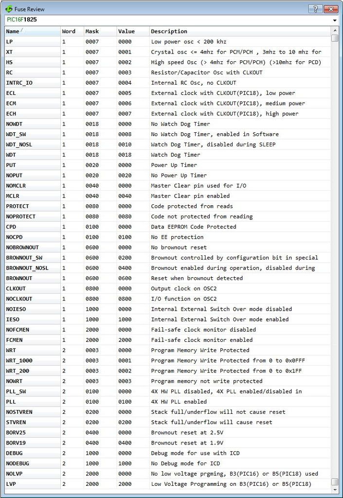
I am looking first at the configuration words/bits inside the compiler:
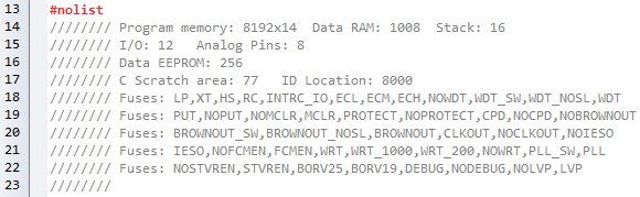
And then inside the file header 16F1825.h:
I open the datasheet of PIC16F1825 (http://ww1.microchip.com/downloads/en/DeviceDoc/40001440E.pdf) and I set on paper each bit, then I get:
| Quote: | 1) Configuration Word 1:
Bit13 - FCMEN = 0
Bit12 - IESO = 0
Bit11 - !CLKOUTEN = 0
Bit10-9 - BOREN<1:0> = 11
Bit8 - !CPD = 1
Bit7 - ! CP = 1
Bit6 - MCLRE = 0
Bit5 - ! PWRTE = 1
Bit4-3 - WDTE<1:0> = 00
Bit2-0 - FOSC<2:0> = 100
Then CONFIG1 = 00011110100100 = 0x7A4
2) Configuration Word 2:
Bit13 - LVP = 0
Bit12 - !DEBUG = 1
Bit11 - Unimplemented = 1
Bit10 - BORV = 1
Bit9 - STVREN = 0
Bit8 - PLLEN = 1
Bit7-5 - Unimplemented = 111
Bit4 – Reserved = 1
Bit3-2 - Unimplemented = 11
Bit1-0 - WRT<1:0> = 11
Then CONFIG2 = 01110111111111 = 0x1DFF |
For test purpose I enable CLKOUT signal to see the Fosc/4=8MHz on oscilloscope and I use next test code:
| Code: | #include <16F1825.h>
#fuses NOFCMEN ,NOIESO, CLKOUT, BROWNOUT, NOCPD, NOPROTECT, NOMCLR, NOPUT, NOWDT, INTRC_IO
#fuses NOLVP, NODEBUG, BORV19, NOSTVREN, PLL, NOWRT
#use delay(clock=32M)
void main() {
setup_adc(ADC_OFF);
disable_interrupts(GLOBAL);
while(TRUE){
output_toggle(PIN_A0);
}
} |
After I compile, I look at the .LST file as recommended here:
https://ccsinfo.com/forum/viewtopic.php?t=52069&highlight=16f1825
and I see always, no matter how I set the PLL in #fuses, as follows:
| Code: | Configuration Fuses:
Word 1: 07A4 INTRC_IO NOWDT NOPUT NOMCLR NOPROTECT NOCPD BROWNOUT CLKOUT NOIESO NOFCMEN
Word 2: 1CFF NOWRT PLL_SW NOSTVREN BORV19 NODEBUG NOLVP |
My observation here is related with Configuration Word 2, which is 0x1CFF indicating the PLLEN bit is set 0, but I want it 1, because I want the CONFIG2 = 01110111111111 = 0x1DFF and the PLL to be used hardware and not software.
My question is how do we set PLL hardware and not software in #fuses? …because the PLLEN bit seems always 0 and the PLL always software (PLL_SW). |
|
 |
temtronic
Joined: 01 Jul 2010
Posts: 9606
Location: Greensville,Ontario
|
|
| Posted: Tue Jan 24, 2017 7:53 am |
|
|
hmm... section 5.2.2.6 in the datasheet does show 4 steps that must be taken to get 32MHz operation using the internal oscillator.
You should post your compiler version as it is possible it's not setting the bits up correctly.
Also, maybe, specify clock=internal in the use delay. This is where the compiler _might_ be getting confused. I didn't write the compiler asnd I don't use that PIC but my 'gut' says it could be a compiler 'bug'. That's why it's critical to say what version you're using.
From the simplifed diagram 5-1, you do need to spec the internal 8 MHz oscillator to feed the PLL....,so again, it looks like a compiler bug' ?
Jay |
|
|
jeremiah
Joined: 20 Jul 2010
Posts: 1401
|
|
| Posted: Tue Jan 24, 2017 8:00 am |
|
|
Try changing your #use delay() to:
| Code: |
#use delay(internal=8000000,clock=32000000)
|
Normally if you specify anything other than "clock" it will try and change the fuses behind the scenes for you to get the configuration right. If your setup is bugged, this might be also, but it is something to try.
If it is bugged, end CCS an email so they can get you a fix. |
|
|
viki2000
Joined: 08 May 2013
Posts: 233
|
|
| Posted: Tue Jan 24, 2017 8:16 am |
|
|
@jeremiah
I have tried your suggestion, but still PLL_SW in .LST file.
@temtronic
Version 5.024 |
|
|
temtronic
Joined: 01 Jul 2010
Posts: 9606
Location: Greensville,Ontario
|
|
| Posted: Tue Jan 24, 2017 10:46 am |
|
|
hmm..
re-reading this post....
this...
For test purpose I enable CLKOUT signal to see the Fosc/4=8MHz on oscilloscope and I use next test code:
This implies Fosc IS 32MHz........
So now I'm confused as to how you decided the PIC isn't running at 32MHz.
Jay |
|
|
viki2000
Joined: 08 May 2013
Posts: 233
|
|
| Posted: Tue Jan 24, 2017 11:44 am |
|
|
I never said the clock is not 32MHz.
My problem is with PLL hardware vs. PLL software setting in “#fuses”
The PLLEN bit is always 0, PLL is always PLL_SW, no matter how we set the fuses.
I want the CONFIG Word 2 to be 0x1DFF and is always 0x1CFF. |
|
|
PCM programmer
Joined: 06 Sep 2003
Posts: 21708
|
|
| Posted: Tue Jan 24, 2017 12:43 pm |
|
|
Even this fails. That's with vs. 5.066.
| Code: | #include <16F1825.h>
#fuses 1=0x3FC4
#fuses 2=0xDF00
#use delay(clock=32M)
//======================
void main()
{
while(TRUE);
} |
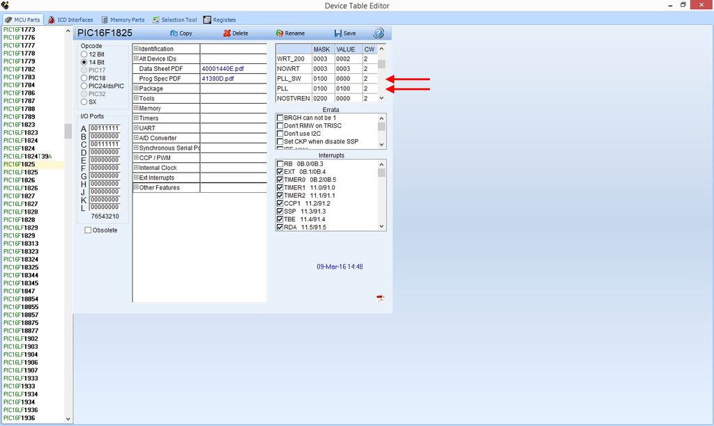
If you have the full IDE version of the compiler, use the Device Editor
to edit the PICs database and make it work if possible. My guess is
there is probably no Config bit listed there in CCS's database for the PLL
bit, and it's probably hard-coded as 0. You could make an entry. |
|
|
viki2000
Joined: 08 May 2013
Posts: 233
|
|
| Posted: Tue Jan 24, 2017 1:41 pm |
|
|
Do you mean this section?
 |
|
|
PCM programmer
Joined: 06 Sep 2003
Posts: 21708
|
|
|
temtronic
Joined: 01 Jul 2010
Posts: 9606
Location: Greensville,Ontario
|
|
| Posted: Tue Jan 24, 2017 5:05 pm |
|
|
OK, I must be missing 'something' here but in looking at the clock block diagram, the ONLY possible way I see to get 32MHz operation using the internal oscillator IS to use the 4x PLL module. So if the PIC is running at 32MHz on the internal oscillator, it really doesn't matter what the 'fuses' config is as the compiler has set whatever is needed to get 32MHz ?
Wish I had a chip to 'play' with...things like this do strain the brain !
Jay |
|
|
viki2000
Joined: 08 May 2013
Posts: 233
|
|
| Posted: Tue Jan 24, 2017 5:08 pm |
|
|
In the table above with Device Table Editor I can change values, but it seems without sense to change a value as long as they indicate good values and good masks and the PLL and PLL-SW are present in the table.
In fact the table above shows the same content as my first picture from top with Fuse Review and PLL and PLL_SW show the proper values.
The problem is that only PLL_SW is used/applied, even if also PLL is shown proper in the table above. Nothing is missing or wrong shown in my opinion.
I should inform CCS Technical Support. |
|
|
viki2000
Joined: 08 May 2013
Posts: 233
|
|
| Posted: Tue Jan 24, 2017 5:13 pm |
|
|
@temtronic
If you would have a PIC to play with, what kind of tests would you make? |
|
|
Ttelmah
Joined: 11 Mar 2010
Posts: 20005
|
|
| Posted: Wed Jan 25, 2017 2:31 am |
|
|
This has been answered here before.
You have to read the data sheet very carefully. The internal oscillator if selected in HFINTOSC mode, always wakes up at 500KHz.
From the data sheet:
| Quote: |
Note: Following any Reset, the IRCF<3:0> bits
of the OSCCON register are set to ‘0111’
and the frequency selection is set to
500 kHz. The user can modify the IRCF
bits to select a different frequency
|
Now if you look, the 500KHz branch does not connect to the PLL. So to use if at 32Mhz with the internal oscillator, you have to wake at 500KHz, then reprogram the oscillator to 8MHz, and enable the PLL.
Again from the data sheet:
| Quote: |
5.2.2.6 32 MHz Internal Oscillator
Frequency Selection
The Internal Oscillator Block can be used with the
4xPLL associated with the External Oscillator Block to
produce a 32 MHz internal system clock source. The
following settings are required to use the 32 MHz
internal clock source:
• The FOSC bits in Configuration Word 1 must be
set to use the INTOSC source as the device
system clock (FOSC<2:0> = 100).
• The SCS bits in the OSCCON register must be
cleared to use the clock determined by
FOSC<2:0> in Configuration Word 1
(SCS<1:0> = 00).
• The IRCF bits in the OSCCON register must be
set to the 8 MHz HFINTOSC set to use
(IRCF<3:0> = 1110).
• The SPLLEN bit in the OSCCON register must be
set to enable the 4xPLL, or the PLLEN bit of the
Configuration Word 2 must be programmed to a
‘1’.
The 4xPLL is not available for use with the internal
oscillator when the SCS bits of the OSCCON register
are set to ‘1x’. The SCS bits must be set to ‘00’ to use
the 4xPLL with the internal oscillator.
|
Note what it says in the last paragraph. You cannot 'hardware' set the PLL to work with the internal oscillator. It has to be set to the software enable mode.
So CCS here are following the data sheet 'to the letter', and to give you 32MHz, set the PLL to software enable, and are then switching this after the chip wakes. |
|
|
viki2000
Joined: 08 May 2013
Posts: 233
|
|
| Posted: Wed Jan 25, 2017 4:20 am |
|
|
I have read that section in the datasheet quite a lot. It is not foreign to me, because I have tested different codes with PIC16F1825 using also XC8 compiler.
Maybe I just do not understand how do you apply it to CCS C compiler.
Could you please provide a code example how to set the fuses in order to get PLL in .LST instead of PLL_SW? |
|
|
Ttelmah
Joined: 11 Mar 2010
Posts: 20005
|
|
| Posted: Wed Jan 25, 2017 4:50 am |
|
|
Use an external crystal.....
It'll then allow you to select PLL in the hardware.
Since the hardware PLL cannot be used on boot, with the internal oscillator, it doesn't let you select it.
Selecting it does nothing with the internal oscillator, since it always boots at a speed which doesn't select the PLL. You have to reprogram the clock to use the PLL. |
|
|
|


