 |
 |
| View previous topic :: View next topic |
| Author |
Message |
Huriz
Joined: 31 May 2012
Posts: 13


|
| [SOLVED]Problems with uart+IR transmission |
 Posted: Sun Dec 02, 2012 12:48 pm Posted: Sun Dec 02, 2012 12:48 pm |
 |
|
In the last post you have the solution for my problems, thanks everybody
##############################################
Hi everybody, I'm trying to make a uart+ir transmitter but I'm having some problems and I don't know where.
Ffirst at all, I'm using these:
CCS 4.093 version
Pic 12F683
Pickit 2
My code is this, (I have 2 codes, one with 4mhz internal clock and the other one with 8mhz internal clock, with different pwm, but finally with the same period of 38khz).
| Code: |
#include <12f683.h>
#include <string.h>
#fuses NOWDT,NOPROTECT,NOCPD,NOMCLR,PUT,INTRC_IO,NOBROWNOUT
//#use delay(internal=8M)
#use delay(internal=4M)
#use rs232(baud=9600, xmit=PIN_A0, RCV=PIN_A1,stop=1,bits=8,parity=N,)
void main()
{
//setup_ccp1(CCP_PWM);
//setup_timer_2(T2_DIV_BY_1,52,1); // 38Khz output (8Meg clock)
//set_pwm1_duty(106L);
setup_ccp1(CCP_PWM);
setup_timer_2(T2_DIV_BY_1, 25, 1); // 38Khz output (4Meg clock)
set_pwm1_duty(13);
setup_timer_1(T1_DISABLED);
setup_comparator(NC_NC_NC_NC);
setup_vref(FALSE);
port_a_pullups(true);
set_tris_a(0x02);
while(1)
{
printf("hello word");
}
}
|
and my board is like this:

Any idea why where could be the problem?
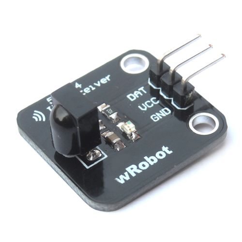
In the other side I have a 38khz receiver with 3 pins (VCC,GND,DATA), connected to the Pickit 2 directly with the UART TOOL.
Last edited by Huriz on Tue Dec 04, 2012 3:47 pm; edited 2 times in total |
|
 |
Ttelmah
Joined: 11 Mar 2010
Posts: 19529
|
|
| Posted: Sun Dec 02, 2012 1:43 pm |
|
|
First, no smoothing shown on the supply. You need a _lot_, especially with your 12R driver for the LED. Can your LED survive the sort of current you are trying to drive it at?. Assuming a typical Vf, you seem to be pushing about 60mA RMS....
Best Wishes |
|
|
Huriz
Joined: 31 May 2012
Posts: 13
|
|
| Posted: Sun Dec 02, 2012 2:48 pm |
|
|
Sorry, I can't understand what do you mean with "no smoothing shown on the supply".
What is _lot_?
Yes it can survive with that 12R, the infrared is a small led, it doesn't need too much mA.
Ttelmah, can you let me know where I have the problem? Not in the values of the resistor, I mean in the code or in design of the board,
regards
NOTE: sorry for my english |
|
|
Ttelmah
Joined: 11 Mar 2010
Posts: 19529
|
|
| Posted: Sun Dec 02, 2012 3:11 pm |
|
|
Seriously, you have probably blown the LED.
IR LED's, typically have a Vf of 1.4v. Now your transistor drops say 0.8v when turned on, so you have:
5-(0.8+1.4)v across the resistor.
This gives a peak current of 2.8/12 = 233mA....
Now most small LED's can survive a peak current of perhaps 100mA, and a RMS of 25mA.
Bang.....
On the smoothing, you should be looking to have less than 0.1v fluctuation. With a peak current of nearly 1/4A, and a time interval of 38KHz, you need a minimum of about 300uF, to give this. You also need a capacitor with better HF performance right by the legs of the PIC. Something like a 0.1 ceramic or polyester.
I also don't know the logic of the 1611, without raiding my data sheets, but remember you want the output to go high when both inputs go _low_.
Best Wishes |
|
|
asmallri
Joined: 12 Aug 2004
Posts: 1635
Location: Perth, Australia


|
|
| Posted: Mon Dec 03, 2012 6:42 am |
|
|
| Ttelmah wrote: | Seriously, you have probably blown the LED.
IR LED's, typically have a Vf of 1.4v. Now your transistor drops say 0.8v when turned on, so you have:
5-(0.8+1.4)v across the resistor.
This gives a peak current of 2.8/12 = 233mA....
|
I agree he has probably blown the LED however your maths is wrong because you have confused base-emitter junction voltage (0.7 voltes for a silicon transistor) and the collector-emitter voltage of a saturated transistor which will be of the order of 0.1 volts.
Peak LED current is therefore (5-(0.1 + 1.4) )volts / 12 ohm = 3.5/12 = 291mA
The peak power dissipated in the 12ohm resistor is VI = 3.5 * .291 = 1watt
_________________
Regards, Andrew
http://www.brushelectronics.com/software
Home of Ethernet, SD card and Encrypted Serial Bootloaders for PICs!! |
|
|
Mike Walne
Joined: 19 Feb 2004
Posts: 1785
Location: Boston Spa UK
|
|
| Posted: Mon Dec 03, 2012 8:41 am |
|
|
With a 'scope:-
Can you get an LED flasher to work?
Can you see any signals coming out ot the PIC?
Can you see any signals coming out of the AND gate?
Mike |
|
|
Ttelmah
Joined: 11 Mar 2010
Posts: 19529
|
|
| Posted: Mon Dec 03, 2012 8:53 am |
|
|
| asmallri wrote: | | Ttelmah wrote: | Seriously, you have probably blown the LED.
IR LED's, typically have a Vf of 1.4v. Now your transistor drops say 0.8v when turned on, so you have:
5-(0.8+1.4)v across the resistor.
This gives a peak current of 2.8/12 = 233mA....
|
I agree he has probably blown the LED however your maths is wrong because you have confused base-emitter junction voltage (0.7 voltes for a silicon transistor) and the collector-emitter voltage of a saturated transistor which will be of the order of 0.1 volts.
Peak LED current is therefore (5-(0.1 + 1.4) )volts / 12 ohm = 3.5/12 = 291mA
The peak power dissipated in the 12ohm resistor is VI = 3.5 * .291 = 1watt |
No, that was why I chose 0.8v, rather than 0.6/0.7v. The figure given is the quoted drop from the data sheet, across the c-e connection when delivering 0.25A, for the BC33740. 
Best Wishes |
|
|
Ttelmah
Joined: 11 Mar 2010
Posts: 19529
|
|
| Posted: Mon Dec 03, 2012 10:46 am |
|
|
| Mike Walne wrote: | With a 'scope:-
Can you get an LED flasher to work?
Can you see any signals coming out ot the PIC?
Can you see any signals coming out of the AND gate?
Mike |
Is the 1611, an AND?. If it is the logic will be wrong. Remember for TTL serial, the 'active' state is low. The gate needed is a NOR. May be the remainder of his problem.
Best Wishes |
|
|
Mike Walne
Joined: 19 Feb 2004
Posts: 1785
Location: Boston Spa UK
|
|
| Posted: Mon Dec 03, 2012 11:57 am |
|
|
| Quote: | | Is the 1611, an AND?. |
I've not checked.
I simply went by what's been drawn.
Mike |
|
|
Ttelmah
Joined: 11 Mar 2010
Posts: 19529
|
|
| Posted: Mon Dec 03, 2012 1:07 pm |
|
|
I too haven't checked the part. Not one I use, but assumed the drawing could just be a generic 'logic' form, rather than the correct symbol....
Best Wishes |
|
|
Huriz
Joined: 31 May 2012
Posts: 13
|
|
| Posted: Mon Dec 03, 2012 1:43 pm |
|
|
Is not a 1611, is a 1G11
Here is the link
Before start reading, A and C pins are bridged.
http://www.nxp.com/documents/data_sheet/74LVC1G11.pdf
The IR led works, I have seen with a phone how it works sending signal, i have seen with a kitpic2 the signal too.
Here some pictures, maybe they could be helpful.
UART signal and 38khz pwm

Here just the signal, where you can see i have a 38.4khz and duty of 50%

Here all signals UART, 38khz and after the AND gate

another one with bigger signal (more period)

The transistor that I'm using is a npn, so my final signal will be equal at the AND gate signal, but with more power. |
|
|
Huriz
Joined: 31 May 2012
Posts: 13
|
|
|
Mike Walne
Joined: 19 Feb 2004
Posts: 1785
Location: Boston Spa UK
|
|
| Posted: Mon Dec 03, 2012 3:21 pm |
|
|
OK. You've got some relevant signals.
What's the problem?
You're making us guess. And it's hard work.
Can you detect signal from your IR LED?
Is your problem in the reciever?
Is your signal upside down?
Please tell us, so we can help.
Like I've said in many threads. You're the one with a real board in front of you. We're not going to duplicate it. So make it easy for us to help you.
Mike |
|
|
Ttelmah
Joined: 11 Mar 2010
Posts: 19529
|
|
| Posted: Mon Dec 03, 2012 3:29 pm |
|
|
If you look, the example driving an NPN transistor uses a NOR. This is what is needed. To use a NAND, you need to be using a PNP transistor.
The signal traces you show are generating pulse trains when they shouldn't....
Best Wishes |
|
|
Huriz
Joined: 31 May 2012
Posts: 13
|
|
| Posted: Mon Dec 03, 2012 3:35 pm |
|
|
ok
I have this receiver that it works with 38khz
My problem is that im not receiving what I would like. and i dont know if the reason is the board that i have done or the code (too much speed).
My problem is that i have seen too much board on internet, but i dont know wich one is the right one, for this reason i took the first board, but i changed the transistor and the AND gate, making the same signal but with differents part (transistor and the AND gate)
up signal = my UART singla
middle = pulses of 38khz
down = is after the transsistor what the IR diode has. (final signal)
i know that im the unique one who has the board in front of, but sometimes is little bit difficult explain what i want, and more with my poor english.
I think that my problem could be in the board, and not in the code, because i have test the code with another pic using a wire, and it works fine, and if i put the kitpic2 in the uart mode, i cant read what im sending. so the problems could be in the board or in the speed, (i mean that the IR transmision needs less speed than 9800 baud rate)
I have bought another receiver, the receiver is directly conected to the pic, because i understood that the receiver give to the pic a clear code, as a UART.
im trying to put all that i can, i have put pictures and if you need anything else, just let me know.
regards and thank you very much
Last edited by Huriz on Mon Dec 03, 2012 3:43 pm; edited 1 time in total |
|
|
|
|
You cannot post new topics in this forum
You cannot reply to topics in this forum
You cannot edit your posts in this forum
You cannot delete your posts in this forum
You cannot vote in polls in this forum
|
Powered by phpBB © 2001, 2005 phpBB Group
|


