 |
 |
| View previous topic :: View next topic |
| Author |
Message |
hoangdinh86
Joined: 18 Dec 2011
Posts: 7
Location: Vietnam


|
| can not write,read again from SPI flash w/ 18F2550 |
 Posted: Sun Dec 18, 2011 10:09 am Posted: Sun Dec 18, 2011 10:09 am |
 |
|
Hi. I've been trying this to work but not success. First times, I could wrote a character to Flash and read it right, but second times I couldn't wrote another character to flash and read it wrong. I am using 18f2550 and A25L80P 8Mbit Flash SPI.
Here is my code:
//main.h
| Code: | #include <18F2550.h>
//configure a 20MHz crystal to operate at 48MHz
#fuses HS,NOWDT,NOPROTECT,NOLVP,NODEBUG,USBDIV,PLL5,CPUDIV1,VREGEN
//#fuses USBDIV, PLL1, CPUDIV1, PROTECT, NOCPD, noBROWNOUT,HSPLL,NOWDT,nolvp, VREGEN
#use delay(clock=20000000)
#include <usb_cdc.h>
#include <25L80.c>
void main() {
char RcvUSB,Rcv;
#use standard_io(A)
usb_cdc_init();
usb_init();
init_ext_eeprom();
output_bit( PIN_A0, 1);
erase_ext_eeprom();
output_bit( PIN_A0, 0);
while(!usb_cdc_connected()) {}
do {
usb_task();
if (usb_enumerated()) {
printf(usb_cdc_putc, "\r\nType a character : !");
RcvUSB = usb_cdc_getc();
write_ext_eeprom(1, RcvUSB);
delay_ms(250);
output_bit( PIN_A0, 1);
delay_ms(250);
output_bit( PIN_A0, 0);
Rcv=read_ext_eeprom(1);
usb_cdc_putc(Rcv);
}
} while (TRUE);
} |
//25L80.c
| Code: | #ifndef EEPROM_SELECT
#define EEPROM_SELECT PIN_B0
#define EEPROM_CLK PIN_B1
#define EEPROM_DI PIN_B2
#define EEPROM_DO PIN_B4
#endif
#define EEPROM_ADDRESS int32
#define EEPROM_SIZE 1048576
void init_ext_eeprom() {
output_high(EEPROM_SELECT);
output_low(EEPROM_DI);
output_low(EEPROM_CLK);
}
BOOLEAN ext_eeprom_ready() {
BYTE cmd[1], i, data;
cmd[0] = 0x05; //rdsr opcode
output_low(EEPROM_SELECT);
for(i=1; i<=8; ++i) {
output_bit(EEPROM_DI, shift_left(cmd,1,0));
output_high(EEPROM_CLK); //data latches
output_low(EEPROM_CLK); //back to idle
}
for(i=1; i<=8; ++i) {
output_high(EEPROM_CLK); //data latches
shift_left(&data,1,input(EEPROM_DO));
output_low(EEPROM_CLK); //back to idle
}
output_high(EEPROM_SELECT);
return !bit_test(data, 0);
}
void erase_ext_eeprom()
{
BYTE i, wren, erase;
wren = 0x06; // wren opcode
erase = 0xc7; // chip erase
// Wait until the eeprom is done with a previous write
while(!ext_eeprom_ready());
output_low(EEPROM_SELECT);
for(i=0; i<8; ++i)
{
output_bit(EEPROM_DI, shift_left(&wren, 1, 0));
output_high(EEPROM_CLK); // data latches
output_low(EEPROM_CLK); // back to idle
}
output_high(EEPROM_SELECT);
output_low(EEPROM_SELECT);
for(i=0; i<8; ++i)
{
output_bit(EEPROM_DI, shift_left(&erase, 1, 0));
output_high(EEPROM_CLK); // data latches
output_low(EEPROM_CLK); // back to idle
}
output_high(EEPROM_SELECT);
delay_ms(40000); // tCE
}
void write_ext_eeprom(EEPROM_ADDRESS address, BYTE data) {
BYTE cmd[5];
BYTE i;
BYTE wren;
wren=0x06;
cmd[0]=data;
cmd[1]=address;
cmd[2]=(address>>8);
cmd[3]=(address>>16);
cmd[4]=0x02;
// Wait until the eeprom is done with a previous write
while(!ext_eeprom_ready());
output_low(EEPROM_SELECT);
for(i=0; i<8; ++i)
{
output_bit(EEPROM_DI, shift_left(&wren,1,0));
output_high(EEPROM_CLK);
output_low(EEPROM_CLK);
}
output_high(EEPROM_SELECT);
output_low(EEPROM_SELECT);
for(i=0; i<40; ++i)
{
output_bit(EEPROM_DI, shift_left(cmd,5,0));
output_high(EEPROM_CLK);
output_low(EEPROM_CLK);
}
output_high(EEPROM_SELECT);
}
BYTE se_ext_eeprom(EEPROM_ADDRESS address) {
BYTE cmd[4];
BYTE i,data;
cmd[0]=address;
cmd[1]=(address>>8);
cmd[2]=(address>>16);
cmd[3]=0xd8;
// Wait until the eeprom is done with a previous write
while(!ext_eeprom_ready());
output_low(EEPROM_SELECT);
for(i=0; i<32; ++i)
{
output_bit(EEPROM_DI, shift_left(cmd,4,0));
output_high(EEPROM_CLK);
output_low(EEPROM_CLK);
}
for(i=0; i<8; ++i)
{
shift_left(&data,1,input(EEPROM_DO));
output_high(EEPROM_CLK);
output_low(EEPROM_CLK);
}
output_high(EEPROM_SELECT);
return(data);
}
BYTE read_ext_eeprom(EEPROM_ADDRESS address) {
BYTE cmd[4];
BYTE i,data;
cmd[0]=address;
cmd[1]=(address>>8);
cmd[2]=(address>>16);
cmd[3]=0x03;
// Wait until the eeprom is done with a previous write
while(!ext_eeprom_ready());
output_low(EEPROM_SELECT);
for(i=0; i<32; ++i)
{
output_bit(EEPROM_DI, shift_left(cmd,4,0));
output_high(EEPROM_CLK);
output_low(EEPROM_CLK);
}
for(i=0; i<8; ++i)
{
shift_left(&data,1,input(EEPROM_DO));
output_high(EEPROM_CLK);
output_low(EEPROM_CLK);
}
output_high(EEPROM_SELECT);
return(data);
} |
A25L80P datasheet
http://www.amictechnology.com/pdf/A25L80P.pdf
Thanks |
|
 |
PCM programmer
Joined: 06 Sep 2003
Posts: 21708
|
|
| Posted: Sun Dec 18, 2011 4:07 pm |
|
|
Post a list of connections between the PIC and the SPI eeprom chip.
Post the Vdd voltage of the PIC, and the Vdd voltage of the SPI eeprom chip.
Also, is this a hardware project or is it Proteus ? |
|
|
hoangdinh86
Joined: 18 Dec 2011
Posts: 7
Location: Vietnam
|
|
| Posted: Sun Dec 18, 2011 8:40 pm |
|
|
Ok. my circuit
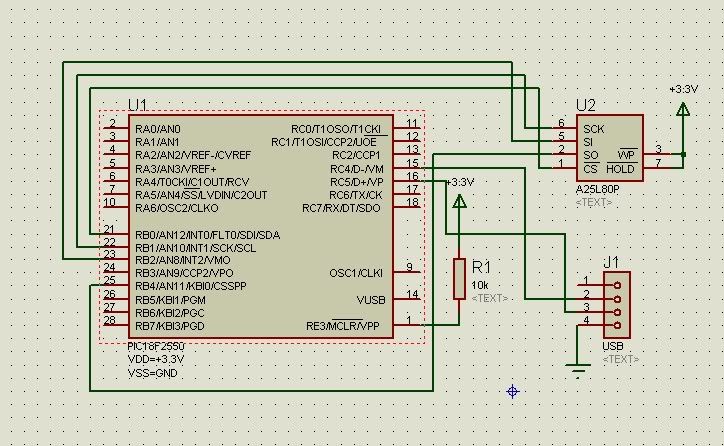
All 3.3V. I use uart usb in 18f2550 <-> PC. |
|
|
cassioriguela
Joined: 25 Oct 2011
Posts: 27
|
|
| Posted: Sun Dec 18, 2011 8:56 pm |
|
|
Hello,
Try to configure spi module by #use spi or setup_spi functions.
Thanks! |
|
|
temtronic
Joined: 01 Jul 2010
Posts: 9459
Location: Greensville,Ontario
|
|
| Posted: Sun Dec 18, 2011 9:27 pm |
|
|
Your schematic shows the 2550 with a VDD of 3.3Volts!
Please check the 18F2550 datasheet, section 28, electrical specs, figure 28-1 and you'll see that the 18F2550 is NOT designed to run at less than 4.2 volts.
While some PICs might run at less than the 4.2V lower limit, it's a 'hit and miss' situation,you might get lucky but unacceptable for any real project(commercial or hobby).Even with correct code, the chip may seem to fail, erratically, for no known reason.
One option is to use the 'L' version, designed for Low voltage operation. |
|
|
hoangdinh86
Joined: 18 Dec 2011
Posts: 7
Location: Vietnam
|
|
| Posted: Sun Dec 18, 2011 9:28 pm |
|
|
Hi. I want to replace SPI HW pins with another pins  . I wonder Vcc : 5V for Pic and Vcc 3.3v cho Flash?. I afraid Flash death because SDI SCL SDO CS(pin B0 B1 B2 B4) 5V from PIC <-> Flash, although Vcc of Flash 3.3V . I wonder Vcc : 5V for Pic and Vcc 3.3v cho Flash?. I afraid Flash death because SDI SCL SDO CS(pin B0 B1 B2 B4) 5V from PIC <-> Flash, although Vcc of Flash 3.3V |
|
|
PCM programmer
Joined: 06 Sep 2003
Posts: 21708
|
|
| Posted: Sun Dec 18, 2011 11:45 pm |
|
|
According to the eeprom data sheet, it requires a 10 ms power-up delay
before the PIC can talk to the eeprom, as shown below:
| Quote: |
POWER-UP AND POWER-DOWN
The device ignores all Write Enable (WREN), Page
Program (PP), Sector Erase (SE), Bulk Erase (BE) and Write
Status Register (WRSR) instructions until a time delay of
tPUW has elapsed after the moment that VCC rises above the
VWI threshold.
Table 6. Power-Up Timing
tpu- Vcc (min) to device operation: 10 ms
|
You could add a delay_ms(10) statement to the end of your
init_ext_eeprom() routine.
They also want you to put a pull-up resistor on the CS pin:
| Quote: |
POWER-UP AND POWER-DOWN
Usually a simple pull-up resistor on Chip Select ( S ) can be
used to insure safe and proper Power-up and Power-down.
|
You could use a 10K pullup (or 4.7K if that's all you have). |
|
|
hoangdinh86
Joined: 18 Dec 2011
Posts: 7
Location: Vietnam
|
|
| Posted: Mon Dec 19, 2011 1:23 am |
|
|
Proteus can't work.still problem.  |
|
|
temtronic
Joined: 01 Jul 2010
Posts: 9459
Location: Greensville,Ontario
|
|
| Posted: Mon Dec 19, 2011 6:55 am |
|
|
great..NOW ..we learn this is NOT real hardware but another 'simulation' with Proteus..
Get rid of Proteus !! it is FULL of bugs,errors,faulty DRCs and will NEVER work correctly.
No one here can FIX problems that Proteus has( we didn't make it, no acess to souce code).
You're wasting valuable time trying to code in Proteus,get real chips and program them with your code just be sure to use compatible devices ! |
|
|
hoangdinh86
Joined: 18 Dec 2011
Posts: 7
Location: Vietnam
|
|
| Posted: Mon Dec 19, 2011 7:23 am |
|
|
yes.real chip.still can not work  .after I used 10k pullup and delay_ms(10) .after I used 10k pullup and delay_ms(10) |
|
|
temtronic
Joined: 01 Jul 2010
Posts: 9459
Location: Greensville,Ontario
|
|
| Posted: Mon Dec 19, 2011 9:37 am |
|
|
It will NEVER work !!!
You cannot directly connect 5V PIC with 3V devices !!!
If you'ld read the datasheets for the 'DC electrical characteristics' you'll see WHY it is NOT possible.
Re-read my 2nd last post about the PIC datasheet section 28. Please read that section or at leat look at the pretty figure that SHOWS the allowable Voltage that a 18F4550 can be used at.
Answer me this question. Does the figure or text say you can run the PIC at 3.3 volts? |
|
|
hoangdinh86
Joined: 18 Dec 2011
Posts: 7
Location: Vietnam
|
|
| Posted: Mon Dec 19, 2011 9:44 pm |
|
|
| Ok. My real hardware work with 3.3v from LM1117-3.3v supply for PIC 18F2550 and Atmel 25C08. Read and write OK, communicate PC /w USB :OK |
|
|
RF_Developer
Joined: 07 Feb 2011
Posts: 839
|
|
| Posted: Tue Dec 20, 2011 3:58 am |
|
|
| hoangdinh86 wrote: | | Ok. My real hardware work with 3.3v from LM1117-3.3v supply for PIC 18F2550 and Atmel 25C08. Read and write OK, communicate PC /w USB :OK |
No, not OK. As others have said over and over, a PIC18F2550 will not work reliably at 3.3V. One might... some of the time. Bits of it might work, others, particularly the USB, might not. It will be temperature dependant. To work reliably at 3.3V you MUST use a PIC18LF2550 and configure it correctly. Even then at 3.3V you can only run the PIC at 20MHz maximum, which is OK as that's what you are trying to run it at. Any faster and you are running it out of specification and it may not work. All this is important if you are intending to build any more than one. You may be able to get one to work, but you'll be lucky to get anymore working.
Also you must follow the recommended USB supply circuit in figure 17.3 and read section 17.2 carefully if you want to ensure the USB works reliably.
RF Developer. |
|
|
hoangdinh86
Joined: 18 Dec 2011
Posts: 7
Location: Vietnam
|
|
| Posted: Tue Dec 20, 2011 4:50 am |
|
|
| Thank. I will buy 18LF2550 and try again |
|
|
|
|
You cannot post new topics in this forum
You cannot reply to topics in this forum
You cannot edit your posts in this forum
You cannot delete your posts in this forum
You cannot vote in polls in this forum
|
Powered by phpBB © 2001, 2005 phpBB Group
|

