| View previous topic :: View next topic |
| Author |
Message |
geolover
Joined: 08 Feb 2011
Posts: 18


|
| SPI mode confusion |
 Posted: Fri Mar 18, 2011 5:12 am Posted: Fri Mar 18, 2011 5:12 am |
 |
|
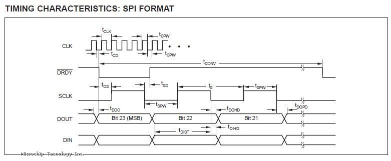
This is the timing diagram of an ADS1271 module outputting data in SPI format
If the above picture isn't showing up then use the link below:
http://www.microchip.com/forums/download.axd?file=0;562791
I'm interfacing this module with my PIC, I got confused by the SPI mode type it is as it wasn't mentioned specifically in page25 of the datasheet, http://focus.ti.com.cn/cn/lit/ds/symlink/ads1271.pdf
my programme is listed below:
| Code: |
#include <24FJ128GA010.h>
#include "stdio.h"
#include "string.h"
#FUSES NOWDT //No Watch Dog Timer
#FUSES NOJTAG //JTAG disabled
#FUSES NOPROTECT //Code not protected from reading
#FUSES NOWRT //Program memory not write protected
#FUSES NODEBUG //No Debug mode for ICD
#FUSES NOCOE //Device will reset into operational mode
#FUSES NOIESO //Internal External Switch Over mode disabled
#FUSES PR //Primary Oscillator
#FUSES CKSNOFSM //Clock Switching is enabled, fail Safe clock monitor is disabled
#FUSES NOOSCIO //OSC2 is clock output
#FUSES XT
#use delay(clock=8000000)
#use rs232(UART1,baud=9600,parity=N,bits=8)
#define AD_SYNC PIN_A0
#define DRDY PIN_A4
#bit frmen1 = 0x0244.15
#bit spifsd1= 0x0244.14
#bit spifpol1 = 0x0244.13
#bit spifsd1 = 0x0244.2
#bit spife1 = 0x0244.1
#bit spisidl2 = 0x0260.13
#bit frmen2 = 0x0264.15
#bit spifsd2 = 0x0264.14
#bit spifpol2= 0x0264.13
#bit spife2 = 0x0264.2
#bit spiben = 0x0264.1
#bit TRISF7 = 0x02DE.7
void main()
{
delay_ms(1);
unsigned char colon= ':';
unsigned char h='h';
unsigned char i='i';
unsigned char t='t';
// int8 i,j;
// int8 ad_samples1[256],ad_samples2[256],ad_samples3[256];
int8 ad_samples1,ad_samples2,ad_samples3;
TRISF7 = 1;
// spisidl2 =0;
// frmen2=1;
// spifsd2=1;
// spifpol2=1;
// spife2=0;
// spiben=0;
set_tris_a(0x10); //A0,A7 output while A4 is input(/DRDY)
setup_spi2(spi_master | spi_l_to_h | spi_clk_div_4);
delay_ms(1);
setup_spi(spi_master | spi_l_to_h| spi_xmit_l_to_h | spi_clk_div_4);
output_low(AD_SYNC);
delay_us(2);
output_high(AD_SYNC);
while(1)
{
output_low(PIN_A6);
while((DRDY==1));
output_high(PIN_A6);
// while(!spi_data_is_in());
// output_low(PIN_A6);
ad_samples1=spi_read2(0x00);
ad_samples2=spi_read2(0x00);
ad_samples3=spi_read2(0X00);
// output_high(PIN_A6);
spi_write(h);
delay_us(100);
spi_write(i);
delay_us(100);
spi_write(t);
delay_us(100);
spi_write(colon);
// spi_write(0x3a);
delay_us(100);
output_low(PIN_A7);
spi_write(ad_samples1);//write 8-bit data into spi
delay_us(100);
spi_write(ad_samples2);
delay_us(100);
spi_write(ad_samples3);
delay_us(100);
output_high(PIN_A7);
// }
}
}
|
My problem is, without connecting anything to the input of the ADC, I should be able to get noise signal in small number, however, I'm receiving data as large as FFFFFA in the DOUT pin, which is essentially negative voltage reference, I began to suspect if my SPI mode is not correct, could anyone take a look for me?
Thank you very much! |
|
 |
FvM
Joined: 27 Aug 2008
Posts: 2337
Location: Germany
|
|
| Posted: Fri Mar 18, 2011 2:08 pm |
|
|
| Quote: | | I'm receiving data as large as FFFFFA in the DOUT pin, which is essentially negative voltage reference |
I don't think so. It's a small negative value:
| Quote: | | The ADS1271 outputs 24 bits of data in two’s complement format. |
|
|
|
geolover
Joined: 08 Feb 2011
Posts: 18
|
| Issues with SDI pin outputting data |
| Posted: Sat Mar 19, 2011 11:43 am |
|
|
Thank you, was being stupid this time....
However, there is an issue related to the SDI pin RF7, it seems RF7 is kept at output state even if I had manually set the tris to input followed by setup_spi() function. Now it will generate 3 continous pulse.... |
|
|
temtronic
Joined: 01 Jul 2010
Posts: 9226
Location: Greensville,Ontario
|
|
| Posted: Sat Mar 19, 2011 12:44 pm |
|
|
I've downloaded the datasheet and it says it's a read only device, so why are you writing to it ?
below code cut from your OP..
spi_write(h);
delay_us(100);
spi_write(i);
delay_us(100);
spi_write(t);
delay_us(100);
spi_write(colon);
// spi_write(0x3a);
delay_us(100);
output_low(PIN_A7);
spi_write(ad_samples1);//write 8-bit data into spi
delay_us(100);
spi_write(ad_samples2);
delay_us(100);
spi_write(ad_samples3);
delay_us(100); |
|
|
geolover
Joined: 08 Feb 2011
Posts: 18
|
|
| Posted: Sat Mar 19, 2011 2:20 pm |
|
|
| temtronic wrote: | I've downloaded the datasheet and it says it's a read only device, so why are you writing to it ?
below code cut from your OP..
spi_write(h);
delay_us(100);
spi_write(i);
delay_us(100);
spi_write(t);
delay_us(100);
spi_write(colon);
// spi_write(0x3a);
delay_us(100);
output_low(PIN_A7);
spi_write(ad_samples1);//write 8-bit data into spi
delay_us(100);
spi_write(ad_samples2);
delay_us(100);
spi_write(ad_samples3);
delay_us(100); |
Apologies, my mistake for not clarifying it.
The spi_write() command send samples received from ADC back to a 18F4550 device then feed into the PC through a USB. |
|
|
temtronic
Joined: 01 Jul 2010
Posts: 9226
Location: Greensville,Ontario
|
|
| Posted: Sat Mar 19, 2011 4:25 pm |
|
|
| Whew , sure glad you cleared that up ! Thought I might have found your problem, but guess that isn't it..... |
|
|
|


