Kerron
Joined: 16 Nov 2010
Posts: 5


|
| Wireless Dual Analog Joystick Controller with an Xbee Module |
 Posted: Tue Dec 28, 2010 3:58 pm Posted: Tue Dec 28, 2010 3:58 pm |
 |
|
This is a Dual Analog Joystick Wireless Controller which provides incremental Remote Control Functions for a Robot that I designed that WORKS VERY WELL!!!!!!!!.
Full Project Code. Robotic Rover & Controller Firmware Code
[url] https://docs.google.com/open?id=0BxR63iu4EZXFNzM4NjNmODMtOGVlZi00ZDE4LWEzMGQtMDVlMzcwMGMxNjRh
[url] http://www.youtube.com/watch?v=tuVESl7Iz60
[url] http://www.youtube.com/watch?v=Q17Afg1u7-4
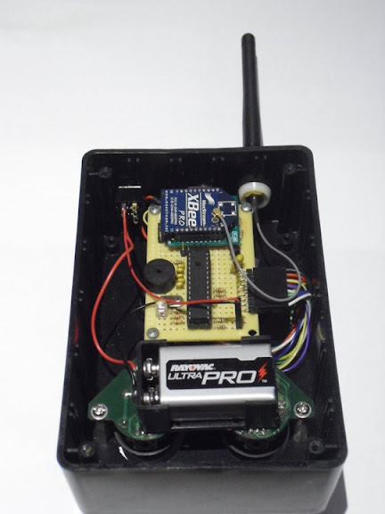
This Project uses the Xbee-Pro-60mW, PIC18F258, 2 Joysticks from a PlayStation 2 Controller & Runs on a 9V Battery
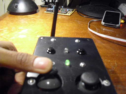
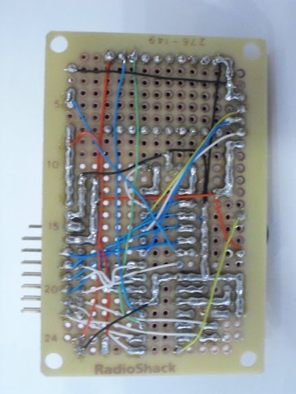
It consists of a dual analog joystick on a PCB board that was removed from a Play Station 2 controller and is wired to 4 analog ports of on a PIC18F258 Microprocessor "or any 28pin PIC with ADC & UART". Each joystick has 2 variable resistors in which one side was connected to +5V & the other to Gnd. The Joystick has a push button which requires a pull up resistor which then is also wired to the PIC Microprocessor . And there are two addition push buttons added to this project. An Xbee RF module is then wired to the PIC TX & RX lines. This project only uses the Xbee module as a transmitter in the future it will be a transceiver There is also a buzzer that generates tones & two leds one white & the other is a bi color red green led.
Dual Analog Joystick Wireless Controller


Board


Robot Rover Project


How The Software Works!!
1) Wait for Xbee to connect to the other Xbee module. Flash the bi color red while it waits 10 seconds. Then Flash Bi color led & play tones.
2) Calibrated Joysticks "find center"
if the joystick is pushed away from center while in calibration a default stored value will be used. if not it will zero out center "more accurate"
MAIN LOOP STARTS
1) Read Both joysticks on the ADC
Read_Joystick();
Then Subtract calibration values from it
2) Do Trig Calculations
Trig_Calc();
R=Sqrt(x2+y2) & Theta=ArcTan(Y/X)
"Cartesian to Polar Conversion"
Theta is where the joystick is pointing & R is magnitude
when greater that a certain magnitude "threshold' get theta
thats the idea!!! Magnitude value is useful for incremental control
3) Check to see if any of the 4 push buttons were pushed
4) Format & Transmit Data over the Air if Flag A = 1 "any activity"
5) Check for inactivity (Flag A = 0 ) & increment counter.
If counter expires put system into sleep mode to save battery power.
The remote can be awaken by pushing either of the push buttons which - triggers and external interrupt.
BACK TO TOP OF THE LOOP
The Transmitted Data Frame Example:
+$$MOVE:U,45,D,20,0,0,0,0* used for my robotic rover project
+$$ is the Header MOVE is the command type for the robot "remote control & camera pan & tilt control simultaneously". Then joystick 1 direction, Joystick1 Magnitude, then joystick 2 direction, Joystick2 Magnitude, then the four push buttons status "toggle" then a '*'\r as a stop sequence.
This can be customized for your project and Encryption & Check Sum can be easily implemented. For remote control you want your data frames to be fast and short if possible.
Memory usage Rom=34% RAM=6% - 10% There allot space left on the Chip
Main Source Code
| Code: |
#include<18f258.h>
#device ADC=10
#fuses HS,NOPROTECT,NOWDT,PUT
#include<stdio.h>
#include <STDLIB.H>
#include<MATH.H>
#use delay(clock=20000000)
#use Rs232 (baud = 57600, xmit= PIN_C6,rcv=PIN_C7,stream=Data)
#include<Functions.C>
int1 wake_sleep=0;
#zero_ram
main() // Main starts
{
delay_ms(10);
for ( i=1;i<=80;++i) //Flash Red Led while XBEE Device connects
{
Bi_Led_OFF;
delay_ms(90);
Bi_RED_ON;
delay_ms(10);
}
delay_ms(1);
for ( i=1;i<=5;++i) // Sound Sequence
{
Bi_Green_ON;
generate_tone (4000,50);
Bi_RED_ON;
generate_tone (7000,50);
}
Bi_Green_ON;
setup_adc_ports(ALL_ANALOG); //Setup analog ports
setup_adc( ADC_CLOCK_INTERNAL); //Setup analog ports
Inactivity = 0 ;
Calibration();
fprintf(Data,"\r\n");
fprintf(Data,"\r\n");
fprintf(Data,"\r\n");
fprintf(Data,"\r\n POWERED UP!!!");
fprintf(Data,"\r\n Software was compiled on ");
printf(__DATE__);
fprintf(Data,"\r\n Designed by Kerron Manwaring");
fprintf(Data,"\r\n Email: Kerron.Manwaring@gmail.com");
fprintf(Data,"\r\n Phone: (914)-830-3542");
fprintf(Data,"\r\n");
fprintf(Data,"\r\n+$$ECHO\r\a");
delay_ms(100);
fprintf(Data,"\r\n DATA FRAME BELOW!!!");
fprintf(Data,"\r\n");
Bi_Led_OFF;
do { // Main Loop Starts
do{ // Loop while Inactivity counter is less the 5000
Read_Joystick();// Read joystick analog port
Trig_Calc(); // Do Trig Math
Actions(); // Check for events "buttons pressed Joystick moved
Transmit(); // Format & Transmit Serialy to Xbee module, if "Flag A=1 activity"
}While(Inactivity++ != 2000); // if inactive for some time "Inactivity == 2000 cycles" Enter into sleep mode
Inactivity=0; // clear timer
for ( i=1;i<=3;++i)// Inactivity sound seguence & Led flashing
{
Bi_Green_ON;
generate_tone (2000,500);
Bi_RED_ON;
}
White_LED_ON;
generate_tone (1000,500);
White_LED_OFF;
Bi_Led_OFF;
fprintf(Data,"\r\n Entering Sleep Mode!!"); // To verify on hyperterminal
fprintf(Data,"\r\n");
fprintf(Data,"+$$AUTO*\r"); // Robot Command Back to Autonomous "Controller is Sleeping" off
enable_interrupts(GLOBAL); // Enable external interrupts
EXT_INT_EDGE(L_to_H);
enable_interrupts(INT_EXT);
enable_interrupts(GLOBAL); // Enable external interrupts
EXT_INT_EDGE(L_to_H);
enable_interrupts(INT_EXT1);
delay_ms(100);
wake_sleep=1; // wake_sleep Flag set to = 1 sleep
sleep(); // Actual Sleep function
}while(true); // Main loop
}
#INT_EXT
void ext_isr()
{
disable_interrupts(INT_EXT); // Button pushed
if (wake_sleep == 1)
{
wake_sleep = 0; // set flag
fprintf(Data,"\r\n Controller Awaken!!"); // To verify on hyperterminal
}
enable_interrupts(INT_EXT);
}
#INT_EXT1
void ext_isr1()
{
disable_interrupts(INT_EXT2); // Button pushed
if (wake_sleep == 1)
{
wake_sleep = 0; // set flag
fprintf(Data,"\r\n Controller Awaken!!"); // To verify on hyperterminal
}
enable_interrupts(INT_EXT2);
}
|
Subroutines Source Code: Functions.C
| Code: |
int1 A=0;
int i;
int16 Inactivity=0;
float Y_2, X_2, Y_1, X_1,M_1,M_2,A_1,A_2,Cal0,Cal1,Cal2,Cal3;
char Dir_1='0', Dir_2='0';
float inc_1=0,inc_2=0;
Char JB1='0',JB2='0',PB1='0',PB2='0';
#define Button_1 PIN_B0
#define Button_2 PIN_B1
#define Joy_Button_1 PIN_C5
#define Joy_Button_2 PIN_C4
#define Tone PIN_C3
// Buzzer
#define BUZZER_ON output_low(PIN_C3)
#define BUZZER_OFF output_High(PIN_C3)
// White LED
#define White_LED_OFF output_low(PIN_C2)
#define White_LED_ON output_High(PIN_C2)
// Bi Color LED
#define Bi_Green_ON output_high(PIN_C1); output_low(PIN_A5)
#define Bi_Red_ON output_low(PIN_C1); output_high(PIN_A5)
#define Bi_Led_OFF output_high(PIN_C1); output_high(PIN_A5)
// Constants
#define Analog_factor 0.09765625
#define Joystick_Thres 9
#define Level 12
////////////////////////////////////////////////////////////////////////////////
void do_delay(int ms_delay, int num_ms, int us_delay, int num_us) // used for generating tones
{
int i;
for(i=0;i<num_ms;i++)
delay_ms(250);
delay_ms(ms_delay);
for(i=0;i<num_us;i++)
delay_us(250);
delay_us(us_delay);
}
////////////////////////////////////////////////////////////////////////////////
void generate_tone(long frequency, long duration) // used for generating tones
{
int32 total_delay_time; // in microseconds
long total_ms_delay_time, total_us_delay_time;
int num_us_delays, num_ms_delays, ms_delay_time, us_delay_time;
long num_periods;
total_delay_time = (1000000/frequency)/2-10; // calculate total delay time (10 for error)
total_ms_delay_time = total_delay_time/1000; // total delay time of ms
num_ms_delays = total_ms_delay_time/250; // number of 250ms delays needed
ms_delay_time = total_ms_delay_time%250; // left over ms delay time needed
total_us_delay_time = total_delay_time%1000; // total delay time of us (ms already acounted for)
num_us_delays = total_us_delay_time/250; // number of 250us delays needed
us_delay_time = total_us_delay_time%250; // left over us delay time needed
num_periods = ((int32)duration*1000)/(1000000/frequency);
while((num_periods--) != 0)
{
do_delay(ms_delay_time, num_ms_delays, us_delay_time, num_us_delays);
output_low(Tone);
do_delay(ms_delay_time, num_ms_delays, us_delay_time, num_us_delays);
output_high(Tone);
}
return;
}
////////////////////////////////////////////////////////////////////////////////////////
////////////////////////////////////////////////////////////////////////////////////////
////////////////////////////////////////////////////////////////////////////////////////
Void Calibration()
{
//////////////// LEFT JOYSTICK # 2 ///////////////
Set_adc_channel(0); // Point to analog port connected to Joystick 2 Y axis
delay_ms(1);
Cal0 = read_adc()*Analog_factor; // Read & Scale
delay_ms(1);
Set_adc_channel(1);; // Point to analog port connected to Joystick 2 X axis
delay_ms(1);
Cal1 = read_adc()*Analog_factor; // Read & Scale
delay_ms(1);
//////////////// RIGHT JOYSTICK # 1 //////////////
Set_adc_channel(2); // Point to analog port connected to Joystick 1 Y axis
delay_ms(1);
Cal2 = read_adc()*Analog_factor; // Read & Scale
delay_ms(1);
Set_adc_channel(3); // Point to analog port connected to Joystick 1 X axis
delay_ms(1);
Cal3 = read_adc()*Analog_factor; // Read & Scale
delay_ms(1);
//////////////////////////////////////////////////
If ((47.9 < Cal0) && (Cal0 < 48.1)) // within the expected range do nothing use actual value "more accurate"
{
}
else
{
Cal0 = 48.0; // Default Center value from testing will be used if the joystick has been touched during calibration or has a slight mechanical malfuction
}
If ((48.7 < Cal1) && (Cal1 < 48.9)) // within the expected range do nothing use actual value "more accurate"
{
}
else
{
Cal1 = 48.8; // Default Center value from testing will be used if the joystick has been touched during calibration or has a slight mechanical malfuction
}
If ((48.7 < Cal2) && (Cal2 < 48.9)) // within the expected range do nothing use actual value "more accurate"
{
}
else
{
Cal2 = 48.8; // Default Center value from testing will be used if the joystick has been touched during calibration or has a slight mechanical malfuction
}
If ((47.5 < Cal3) && (Cal3 < 47.7)) // within the expected range do nothing use actual value "more accurate"
{
}
else
{
Cal3 = 47.6; // Default Center value from testing will be used if the joystick has been touched during calibration or has a slight mechanical malfuction
}
}
/////////////////////////////////////////////////////////////////////////////////
Void Read_Joystick()
{
//////////////// LEFT JOYSTICK # 2 //////////////////
Set_adc_channel(0); // Select Analog port connected to joystick 2 Y axis
delay_ms(1);
Y_2 = ((read_adc()*Analog_factor)-Cal0); // Read,Scale & subtract center value
delay_ms(1);
Set_adc_channel(1); // Select Analog port connected to joystick 2 X axis
delay_ms(1);
X_2 = ((read_adc()*Analog_factor)-Cal1); // Read,Scale & subtract center value
delay_ms(1);
//////////////// RIGHT JOYSTICK # 1 ////////////////
Set_adc_channel(2); // Select Analog port connected to joystick 1 Y axis
delay_ms(1);
Y_1 = ((read_adc()*Analog_factor)-Cal2); // Read,Scale & subtract center value
delay_ms(1);
Set_adc_channel(3); // Select Analog port connected to joystick 1 X axis
delay_ms(1);
X_1 = ((read_adc()* Analog_factor)- Cal3); // Read,Scale & subtract center value
delay_ms(1);
}
////////////////////////////////////////////////////////////////////////////////////////
////////////////////////////////////////////////////////////////////////////////////////
////////////////////////////////////////////////////////////////////////////////////////
Void Trig_Calc() // Math Calculations "Cartesian to Polar Coordinates"
{
A_2 = (atan2(Y_2,X_2))*180/3.14; // Find theta
M_2 = sqrt ((Y_2*Y_2) + (X_2*X_2)); // Find r magnitude
A_2= A_2+180; // Adjust to 0 to 359 degrees
M_2= floor (M_2); // Floor r
A_2= Abs(A_2);
A_1 = (atan2(Y_1,X_1))*180/3.14; // Find theta
M_1 = sqrt ((Y_1*Y_1) + (X_1*X_1)); // Find r magnitude
A_1= A_1+180; //// Adjust to 0 to 359 degrees
A_1= Abs(A_1);
M_1= floor (M_1); // Floor r
}
////////////////////////////////////////////////////////////////////////////////////////
////////////////////////////////////////////////////////////////////////////////////////
////////////////////////////////////////////////////////////////////////////////////////
Void Actions() //Check if any buttons where pressed and where the joysticks where moved
{
if (!input(Joy_Button_1)) // if pressed
{
White_LED_ON; // while led on
if(JB1 == '0') // check previous condition "toggle"
{
JB1='1'; // Toggle Flag & Status
generate_tone (5000,200); // Audio conformation that the buttons was pressed
}
else
{
JB1='0'; // Toggle Flag & Status
generate_tone (2000,200); // Audio conformation that the buttons was pressed
}
White_LED_ON; // while led on
A = 1; // Activity
}
if (!input(Joy_Button_2)) // if pressed
{
White_LED_ON; // while led on
if(JB2 == '0') // check previous condition "toggle"
{
JB2='1'; // Toggle Flag & Status
generate_tone (5000,200); // Audio conformation that the buttons was pressed
}
else
{
JB2='0'; // Toggle Flag & Status
generate_tone (2000,200); // Audio conformation that the buttons was pressed
}
A = 1; // Activity
}
if (!input(Button_1)) // if pressed
{
White_LED_ON; // while led on
if(PB1 == '0') // check previous condition "toggle"
{
PB1='1'; // Toggle Flag & Status
generate_tone (5000,200); // Audio conformation that the buttons was pressed
}
else
{
PB1='0'; // Toggle Flag & Status
generate_tone (2000,200); // Audio conformation that the buttons was pressed
}
A = 1; // Activity
}
if (!input(Button_2)) // if pressed
{
White_LED_ON; // while led on
if(PB2 == '0') // check previous condition "toggle"
{
PB2='1'; // Toggle Flag & Status
generate_tone (5000,200); // Audio conformation that the buttons was pressed
}
else
{
PB2='0'; // Toggle Flag & Status
generate_tone (2000,200); // Audio conformation that the buttons was pressed
}
A = 1; // Activity
}
if (M_1 > Joystick_Thres) // if joystick 1 reading is greater than threhold value find which direction is pushed
{
A = 1; // Activity
// UP
if((A_1 > 45)&&(A_1 < 135)) //A_1 Greater Than 45 & less Than 135
{
Bi_Green_ON; // green led on
Dir_1='L'; // set direction to left
}
// LEFT
if(((A_1 < 45)&&(A_1 >= 0))||((A_1 <= 360)&&(A_1 > 315))) //A_1 less Than 45 & Greater Than 135
{
Bi_Green_ON; // green led on
Dir_1='U'; // set direction to up
}
// DOWN
if((A_1 < 315)&&(A_1 > 225))//A_1 Less Than 315 & A_1 Greater Than 225
{
Bi_Green_ON; // green led on
Dir_1='R'; // set direction to right
}
// RIGHT
if((A_1 > 135 )&&(A_1 < 225))//A_1 Greater Than 135 & A_1 Less Than 225
{
Bi_Green_ON; // green led on
Dir_1='D'; // set direction to down
}
inc_1 = floor(M_1); // adjust the magnitude reading
if (inc_1 > 50) // 50 will be set as the max reading from the center. The range is (Threshold + 1 to 50)
{
inc_1=50;
}
}
if (M_2 > Joystick_Thres) // if joystick 2 reading is greater than threhold value find which direction is pushed
{
A = 1;
// UP
if((A_2 > 45)&&(A_2 < 135)) //A_1 Greater Than 45 & less Than 135
{
Bi_Green_ON; // green led on
Dir_2='L'; // set direction to left
}
// LEFT
if(((A_2 < 45)&&(A_2 >= 0))||((A_2 <= 360)&&(A_2 > 315))) //A_1 less Than 45 & Greater Than 135
{
Bi_Green_ON; // green led on
Dir_2='U'; // set direction to up
}
// DOWN
if((A_2 < 315)&&(A_2 > 225))//A_1 Less Than 315 & A_1 Greater Than 225
{
Bi_Green_ON; // green led on
Dir_2='R'; // set direction to right
}
// RIGHT
if((A_2 > 135 )&&(A_2 < 225))//A_1 Greater Than 135 & A_1 Less Than 225
{
Bi_Green_ON; // green led on
Dir_2='D'; // set direction to down
}
inc_2 = floor(M_2); // adjust the magnitude reading
if (inc_2 > 50) // 50 will be set as the max reading from the center. The range is (Threshold + 1 to 50)
{
inc_2=50;
}
}
}
////////////////////////////////////////////////////////////////////////////////////////
////////////////////////////////////////////////////////////////////////////////////////
////////////////////////////////////////////////////////////////////////////////////////
Void Transmit() // Transmit data if activity flag A == 1
{
if (A == 1)
{
output_high(Pin_C1);//RTS
delay_ms(1); //delay
fprintf(Data," +$$MOVE:%c,%2.0f,%c,%2.0f,%C,%C,%C,%C*\r",Dir_1,inc_1,Dir_2,inc_2,JB1,JB2,PB1,PB2); // Transmit Data frame to Xbee module
delay_us(1); //delay
output_low(Pin_C1);//RTS
Dir_1 = 'X'; // clear variable
Dir_2 = 'X'; // clear variable
inc_1 = 0 ; // clear variable
inc_2 = 0 ; // clear variable
A = 0; // clear flag "actions flag"
White_LED_OFF; // white leed off if it was on
Bi_Led_OFF; // led off
BUZZER_OFF; // buzzer off
Inactivity = 0; // clear inactivity counter
delay_us(1); // delay
}
}
|
Test it out with an Xbee module connected to Hyper Terminal.
Kerron Manwaring
[/url]
Last edited by Kerron on Thu Jan 16, 2014 12:40 pm; edited 4 times in total |
|


