 |
 |
| View previous topic :: View next topic |
| Author |
Message |
SuperDave
Joined: 22 May 2008
Posts: 63
Location: Madison, TN


|
| MAX6954 - KeyScan - SPI - Picmicro |
 Posted: Fri May 28, 2010 12:08 pm Posted: Fri May 28, 2010 12:08 pm |
 |
|
Having flogged this for several weeks thru Maxim here's some not so well known but important bits of information.
If you're doing KeyScan the supply to the MAX6954 cannot be higher than 4.50 Volts or you will get garbage readings. Crazy but true, come count my gray hairs on this one. A simple power diode (which will handle the led current and resulting heat) works well here along with a local buffer capacitor to reduce 5 Volts below the 4.5 Volt limit. A diode is better than the spec sheet suggested heat reducing resistor since the diode will drop the voltage more consistently.
The peculiar requirement for SPI in the MAX6954 which needs the clock to come in low and go out high relative to enable was solved this way.
| Code: |
int16 xfer_panel(int16 a) {
//no Enable= in use spi
#use spi (master,CLK=mClk,DI=mMISO,DO=mMOSI, Mode=0,bits=15,msb_first,stream=Panel)
int16 iData;
short bLastBit;
output_low(mEnable);
// curiously spi_xfer sends the LEAST significant 15 bits in MSB order, so >> is required
iData = spi_xfer(Panel,a >> 1); //MSB 15 sent and received
if (bit_test(a,0)) { //setup the last bit
output_high(mMOSI);
} else {
output_low(mMOSI);
}
output_high(mClk); //clock high
bLastBit = input_state(mMISO); //get the last input bit
output_high(mEnable); //now enable high
output_low(mClk); //done, set the clock back low
// and spi_xfer loads the least significant 15 bits in MSB order so << is required.
iData = iData << 1 | bLastBit; //figure the return
return(iData);
}
|
Enjoy. |
|
 |
SuperDave
Joined: 22 May 2008
Posts: 63
Location: Madison, TN
|
|
| Posted: Mon Jun 07, 2010 10:32 am |
|
|
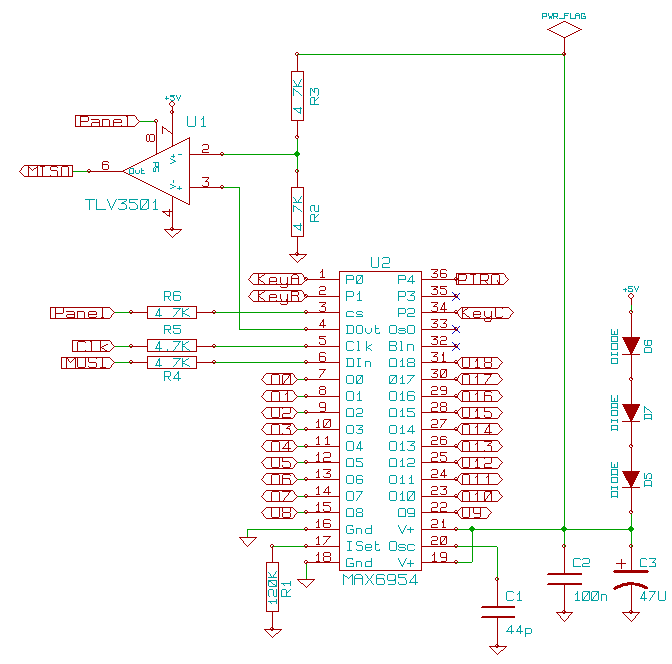
Further emails from Maxim indicate that 4.5 Volts may not be low enough for KeyScan operation if leds are actually being driven by the circuit and that the KeyScan detection threshold is dependent on the voltage of the leds!!! Since I don't have the leds available at this moment but I know that there are 48 of them of various colors (ie. various voltages), my choice was to lower the voltage down to about 3 Volts as a worst case design. This has the benefit of reducing the heat dissipation in the MAX3954 or more accurately sharing the heat dissipation with other components but in any event keeping individual chip temperatures cooler. But there are three significant problems:
1. Reducing the 5 Volts to a 3 Volt supply (closer to 3.2 Volts) is handled by three power diodes D5-7 on the schematic below. (D0-D4 are 14 segment displays, not shown). C2, 3 provide local filtering. Cheap AC power diodes are fine since there are no reverse voltage or recovery issues. They do need to handle about an amp if lots of bright leds are used.
2. The 5 Volt logic from the Pic will either be clamped by the 3 Volt logic of the Max and fail to drive other 5 Volt logic chips on the SPI bus or will blow the Max, neither of which are desirable. This is fairly easily solved by the three resistors R4-6 on the schematic which allow the Pic to output a full 5 Volts and limit the input current to the Max MOSI, Clk and CS pins.
3. Finally the 3 Volt logic of the Max will not provide a high to the 5 Volt Schmidt trigger inputs of the Pic which require 4 Volts as a high. This is a concern on two lines, MISO and IRQ. The IRQ (PIRQ on the schematic) is an open drain on the Max and goes to Port B0 on the Pic. If the Port B pullups are enabled or a pullup resistor is connected from B0 to 5 Volts, that problem is solved. But MISO is a push-pull output which (for reasons Maxim tries to defend somewhat unsuccessfully) NEVER tristates in violation of the SPI recommendations. The Maxim recommended 74AHC1G125 also will not trigger on 3 Volt logic.
An obvious quick solution is a comparator such as the LM339 with its inverting input driven by 1.5 Volts and its non inverting input driven by both the MISO line through a resistor and by Enable through a diode. Logically it works but it doesn't begin to be fast enough at typical SPI speeds. The solution shown on the schematic is a high speed, tristate comparator on the MISO line. Resistors R2, 3 provide the half supply reference.
 |
|
|
|
|
You cannot post new topics in this forum
You cannot reply to topics in this forum
You cannot edit your posts in this forum
You cannot delete your posts in this forum
You cannot vote in polls in this forum
|
Powered by phpBB © 2001, 2005 phpBB Group
|

